User Guide Site Master S331E, S332E, S361E, and S362E C or al -i So lu tio ns Cable and Antenna Analyzer Spectrum Analyzer
ns tio lu So -i al or C Anritsu Company 490 Jarvis Drive Morgan Hill, CA 95037-2809 P/N: 10000-00000 Revision: Prelim Printed: January 2011
User Guide Site Master Cable and Antenna Analyzer with Spectrum Analyzer tio ns S331E, 2 MHz to 4 GHz S332E, 2 MHz to 4 GHz, Spectrum Analyzer, 100 kHz to 4 GHz S361E, 2 MHz to 6 GHz S362E, 2 MHz to 6 GHz, Spectrum Analyzer, 100 kHz to 6 GHz C or al -i So lu Appendix A provides a list of supplemental documentation for the Site Master features and options. The documentation set is available as PDF files on the documentation disc and the Anritsu web site.
WARRANTY The Anritsu product(s) listed on the title page is (are) warranted against defects in materials and workmanship for one year from the date of shipment. Anritsu’s obligation covers repairing or replacing products which prove to be defective during the warranty period. Buyers shall prepay transportation charges for equipment returned to Anritsu for warranty repairs. Obligation is limited to the original purchaser. Anritsu is not liable for consequential damages.
-i al or C ns tio lu So
-i al or C ns tio lu So
CE Conformity Marking Anritsu affixes the CE Conformity marking onto its conforming products in accordance with Council Directives of The Council Of The European Communities in order to indicate that these products conform to the EMC and LVD directive of the European Union (EU).
-i al or C ns tio lu So
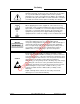
Safety Symbols To prevent the risk of personal injury or loss related to equipment malfunction, Anritsu Company uses the following symbols to indicate safety-related information. For your own safety, please read the information carefully before operating the equipment. Symbols Used in Manuals Danger This indicates a very dangerous procedure that could result in serious injury or death, or loss related to equipment malfunction, if not performed properly.
For Safety Warning Always refer to the operation manual when working near locations at which the alert mark, shown on the left, is attached. If the operation, etc., is performed without heeding the advice in the operation manual, there is a risk of personal injury. In addition, the equipment performance may be reduced. Moreover, this alert mark is sometimes used with other marks and descriptions indicating other dangers.
Table of Contents Chapter 1—General Information 1-1 Introduction . . . . . . . . . . . . . . . . . . . . . . . . . . . . . . . . . . . . . . . . . . . . . . . . . 1-1 1-2 Chapter Overview . . . . . . . . . . . . . . . . . . . . . . . . . . . . . . . . . . . . . . . . . . . . 1-1 1-3 Available Models. . . . . . . . . . . . . . . . . . . . . . . . . . . . . . . . . . . . . . . . . . . . . 1-1 1-4 Available Options . . . . . . . . . . . . . . . . . . . . . . . . . . . . . . . . . . . . . . . . . . . .
Table of Contents (Continued) 2-7 Symbols and Indicators. . . . . . . . . . . . . . . . . . . . . . . . . . . . . . . . . . . . . . . 2-11 Calibration Symbols. . . . . . . . . . . . . . . . . . . . . . . . . . . . . . . . . . . . . . . 2-11 Battery Symbols. . . . . . . . . . . . . . . . . . . . . . . . . . . . . . . . . . . . . . . . . . 2-11 Additional Symbols . . . . . . . . . . . . . . . . . . . . . . . . . . . . . . . . . . . . . . . 2-12 2-8 Data Entry . . . . . . . . . . . . . . . . . . . . . . . .
Table of Contents (Continued) Chapter 4—File Management Introduction . . . . . . . . . . . . . . . . . . . . . . . . . . . . . . . . . . . . . . . . . . . . . . . . . 4-1 4-2 Managing Files . . . . . . . . . . . . . . . . . . . . . . . . . . . . . . . . . . . . . . . . . . . . . . 4-1 Save Files . . . . . . . . . . . . . . . . . . . . . . . . . . . . . . . . . . . . . . . . . . . . . . . 4-1 Save Dialog Box . . . . . . . . . . . . . . . . . . . . . . . . . . . . . . . . . . . . . . . . . .
Table of Contents (Continued) Chapter 7—Ethernet Connectivity (Option 411) 7-1 Introduction . . . . . . . . . . . . . . . . . . . . . . . . . . . . . . . . . . . . . . . . . . . . . . . . 7-1 7-2 Ethernet Connection . . . . . . . . . . . . . . . . . . . . . . . . . . . . . . . . . . . . . . . . . . 7-1 Network Connection . . . . . . . . . . . . . . . . . . . . . . . . . . . . . . . . . . . . . . . 7-1 Ethernet Direct Connection . . . . . . . . . . . . . . . . . . . . . . . . . . . . . . . . . .
Chapter 1 — General Information 1-1 Introduction This chapter provides information about frequency range, available options, additional documents, general overview, preventive maintenance, and annual verification requirements for the Anritsu Handheld S331E, S361E, S332E, and S362E Site Master models. Throughout this manual, the term Site Master will refer to the S331E, S361E, S332E, and S362E.
1-4 Available Options 1-4 General Information Available Options Available options for the Site Master models are shown in Table 1-2. Table 1-2.
General Information 1-5 1-5 Standard Accessories Standard Accessories The Anritsu Site Master includes a one year warranty which includes: battery, firmware, software, and Certificate of Calibration and Conformance. The following items are supplied with the product. Table 1-3.
1-8 General Description 1-8 General Information General Description The Site Master S331E/S361E is a hand held cable and antenna analyzer designed to make Return Loss, VSWR, Cable Loss, and Distance-To-Fault (DTF) measurements in the field. The cable and antenna analyzer also includes 1-port phase and smith chart measurements. The 2-port transmission measurement option includes two power levels and access to a built-in 32 volt bias tee (Option 10).
General Information 1-10 1-11 Calibration Requirements Preventive Maintenance Site Master preventive maintenance consists of cleaning the unit and inspecting and cleaning the RF connectors on the instrument and all accessories. Clean the Site Master with a soft, lint-free cloth dampened with water or water and a mild cleaning solution. Caution To avoid damaging the display or case, do not use solvents or abrasive cleaners.
1-13 ESD Caution 1-13 General Information ESD Caution The Site Master, like other high performance instruments, is susceptible to electrostatic discharge (ESD) damage. Coaxial cables and antennas often build up a static charge, which (if allowed to discharge by connecting directly to the Site Master without discharging the static charge) may damage the Site Master input circuitry. Site Master operators must be aware of the potential for ESD damage and take all necessary precautions.
1-14 Battery Replacement Battery Compartment lu Figure 1-1. tio ns General Information Use only Anritsu Company approved batteries, adapters, and chargers with this instrument. or C Note al -i So The battery that is supplied with the Site Master may need charging before use.
1-15 Soft Carrying Case 1-15 General Information Soft Carrying Case The Site Master can be operated while in the soft carrying case. On the back of the case is a large storage pouch for accessories and supplies. To install the instrument into the soft carrying case: 1. The front panel of the case is secured with hook-and-loop fasteners. Fully close the front panel of the case. When closed, the front panel supports the shape of the case while you are inserting the Site Master. 2.
General Information 1-16 Tilt Bail Stand The soft carrying case includes a detachable shoulder strap, which can be connected to the D-rings of the case. Caution 1-16 The soft case has panel openings for the fan inlet and exhaust ports. Do not block the air flow through the panels when the unit is operating. Tilt Bail Stand A Tilt Bail is attached to the back of the Site Master for desktop operation. The tilt bail provides two settings of backward tilt for improved stability.
1-17 1-17 Secure Environment Workplace General Information Secure Environment Workplace This section details the types of memory in the Site Master, how to delete stored user files in internal memory, and recommended usage in a secure environment workplace. Site Master Memory Types The instrument contains non-volatile disk-on-a-chip memory, EEPROM, and volatile DRAM memory. The instrument does not have a hard disk drive or any other type of volatile or non-volatile memory.
General Information 1-17 Secure Environment Workplace Recommended Usage in a Secure Environment Set the Site Master to save files to an external USB Flash drive: 1. Attach the external Flash drive and turn the instrument on. 2. Press the Shift button then the File (7) button. 3. Press the Save submenu key. 4. Press the Change Save Location submenu key, then select the USB drive with the rotary knob, Up/Down arrow keys, or the touchscreen. 5. Press the Set Location submenu key.
ns tio lu So -i al or C 1-12 PN: 10580-00252 Rev.
Chapter 2 — Instrument Overview 2-1 Introduction This chapter provides a brief overview of the Anritsu Site Master. The intent of this chapter is to acquaint the user with the instrument. For detailed measurement information, refer to a specific measurement guide listed in Appendix A, “Measurement Guides”.
2-4 Front Panel Overview Instrument Overview To turn on the Site Master, press the green On/Off button on the front panel (Figure 2-1) Fan Inlet Port Fan Exhaust Port Touch Screen Submenu Keys Menu Key Calibration Status and Type Shift Key Numeric Keypad/ Shift Menu Keys (1 to 9) Printed in Blue Fan Inlet Port Site Master Overview On/Off Button tio Figure 2-1.
Instrument Overview 2-4 Front Panel Overview Front Panel Keys Menu Key Press this key to display a grid of shortcut icons for installed measurement modes and user selected menus and setup files. Menu Key Screen, Icons for Installed Measurements C Note or al Figure 2-2. -i So lu tio ns Figure 2-2 shows the Menu key screen with shortcut icons for the installed measurement modes. Touch one of the icons in the top two rows to change modes.
2-4 Front Panel Overview Instrument Overview Figure 2-3 shows the Menu key screen with shortcut icons for the installed measurement modes and four rows of user-defined shortcuts to menus and setup files. Menu Key Screen So Figure 2-3. lu tio ns Press and hold down any key for a few seconds to add a shortcut to this screen.To add shortcut setup files (.stp), open the recall menu and hold down on the file name for several seconds. Then select the location for the shortcut.
Instrument Overview 2-4 Front Panel Overview Shift Key Pressing the Shift key and then a number key executes the function that is indicated in blue text above the number key. When the Shift key is active, its icon is displayed at the top-right of the measurement display area by the battery charge indicator. Figure 2-4. Shift Key Icon Number Keypad The Number keypad has two functions: The primary function is number entry. The secondary function of the number keypad is to list various menus.
2-5 Display Overview Instrument Overview LED Indicators Power LED The Power LED is located to the left of the On/Off key. The LED is solid green when the unit is on and slowly blinks when the unit is off but has external power. Charge LED The Charge LED is located to the right of the On/Off key. The LED slowly blinks when the battery is charging and is solid green when the battery is fully charged.
Instrument Overview 2-5 Save GPS Icon Battery Charge Date/Time GPS Location Display Overview Trace Measurement Title Submenu Touch Screen Keys Frequency Standard Marker Table Main Menu Touch Screen Keys Spectrum Analyzer Display (S332E and S362E only) C or al -i Figure 2-6. So lu tio ns Measurement Settings Summary Site Master User Guide PN: 10580-00252 Rev.
2-5 Display Overview Instrument Overview In addition to the default color display, Site Master offers the following display settings: Black & White for printing and viewing in broad daylight conditions Night Vision optimized for night-time viewing ns High Contrast for other challenging viewing conditions Black & White or al -i So lu tio Default Colors High Contrast C Night Vision Figure 2-7. 2-8 Site Master Display Settings PN: 10580-00252 Rev.
Instrument Overview 2-6 2-6 Test Panel Connector Overview Test Panel Connector Overview Test panel connectors for the Site Master S332E are shown in Figure 2-8. External Reference RF In External Trigger USB Mini-B GPS External Power Figure 2-8. S332E Test Panel Connector tio External Power USB Type A ns LAN Headset Jack (Option 0411) RF Out When using the AC-DC Adapter, always use a three-wire power cable that is connected to a three-wire power line outlet.
2-6 Test Panel Connector Overview Instrument Overview USB Interface – Type A The Site Master has two Type A USB connectors that accept USB Flash Memory devices for storing measurements, setups data, and screen images. USB Interface – Mini-B The USB 2.0 Mini-B connector can be used to connect the Site Master directly to a PC. The first time the Site Master is connected to a PC, the normal USB device detection by the computer operating system will take place.
Instrument Overview 2-7 2-7 Symbols and Indicators Symbols and Indicators The following symbols and indicators indicate the instrument status or condition on the display. Calibration Symbols The current calibration status and type is displayed in the upper-left of the screen when in Cable & Antenna Analyzer mode. See Figure 2-5 on page 2-6. The five status messages are described next. Cal Status: ON, Flex The Site Master has been calibrated with discrete Open, Short, and Load components.
2-7 Symbols and Indicators Instrument Overview When either the AC-DC Adapter (40-168-R) or the Automotive Cigarette Lighter Adapter (806-141-R) is connected, the battery automatically receives a charge, and the battery symbol with the lightning bolt is displayed (Figure 2-10). Figure 2-10. Battery Charging Icon The green Charge LED flashes when the battery is charging, and remains on steady when the battery is fully charged.
Instrument Overview 2-8 2-8 Data Entry Data Entry Numeric Values Numeric values are changed using the rotary knob, arrow keys, or the keypad. Pressing one of the main menu keys will display a list of submenus on the right side of the touch screen. When the value on a submenu key is displayed in red, it is ready for changing. When using the rotary knob or arrow keys the changing value is shown on the submenu and in red on the graticule.
2-9 Mode Selector Menu 2-9 Instrument Overview Mode Selector Menu ns To access the functions under the Mode menu, select the Shift key, then the Mode (9) key. Use the directional arrow keys, the rotary knob, or the touch screen to highlight the selection, and press the Enter key to select. The list of modes that appear in this menu will vary depending upon the options that are installed and activated in the instrument. Figure 2-14 is an example of the Mode menu.
Chapter 3 — Quick Start Guide 3-1 Introduction This chapter provides a brief overview of basic measurement setups. For detailed measurement information, refer to a specific measurement guide listed in Appendix A, “Measurement Guides”.
3-3 Cable & Antenna Analyzer 3-3 Quick Start Guide Cable & Antenna Analyzer Set the instrument to Cable & Antenna Analyzer mode as described in the previous section. Select the Measurement Type Measurement Menu al Set the Frequency -i Figure 3-2. So lu tio ns Press the Measurement main menu key and select the appropriate measurement. 1. Press the Freq/Dist main menu key. or 2. Press the Start Freq submenu key and use the keypad, rotary knob, or the arrow keys to enter the start frequency.
Quick Start Guide 3-3 Cable & Antenna Analyzer Turn on Markers 1. Press the Marker main menu key. 2. Press the Marker 1 2 3 4 5 6 submenu key and select the marker number 1 button using the touch screen. The underlined number on the Marker submenu key indicates the active marker. 3. Use the arrow keys, the keypad, or the rotary knob to move the marker. The current value for the selected marker is shown above the upper-left corner of the graph.
3-3 Cable & Antenna Analyzer Quick Start Guide Single Limit Line 1. Press Shift and then Limit (6) to enter the Limit menu. 2. Press the Limit On/Off key to turn on the Limit. 3. Press Single Limit and then use the numeric keypad, the arrow keys, or the rotary knob to change the limit value and then press Enter. Refer to the Cable & Antenna Measurement Guide listed in Appendix A for creating multi-segment limit lines. Note Single Limit Lines C Figure 3-3. or al -i So lu tio ns 4.
Quick Start Guide 3-3 Cable & Antenna Analyzer DTF Setup 1. Press the Measurements main menu key and select DTF Return Loss or DTF VSWR. 2. Press the Freq/Dist main menu key. 3. Press the Units submenu key and select m to display distance in meters or ft to display distance in feet. 4. Press DTF Aid and use the touch screen, or arrow keys to navigate through all the DTF parameters. a. Set Start Distance and Stop Distance. Stop Distance needs to be smaller than Dmax. b.
3-3 Cable & Antenna Analyzer Quick Start Guide Calibrate with OSL Calibration Refer to the Cable & Antenna Measurement Guide listed in Appendix A for calibration details. Note 1. Press the Freq/Dist main menu key and enter the appropriate frequency range 2. Press Shift then Calibrate (2) key. 3. Select Standard or FlexCal. 4. Press Start Cal and follow instructions on screen. 5. Connect Open to RF Out and press the Enter key. 6. Connect Short to RF Out and press the Enter key. 7.
Quick Start Guide 3-4 3-4 Spectrum Analyzer Spectrum Analyzer Set the instrument to Spectrum Analyzer mode as described in Section 3-2 “Measurement Mode Selection” on page 3-1. Set Start and Stop Frequencies 1. Press the Freq main menu key. 2. Press the Start Freq submenu key. 3. Enter the desired start frequency using the keypad, the arrow keys, or the rotary knob. When entering a frequency using the keypad, the submenu key labels change to GHz, MHz, kHz, and Hz. Press the appropriate unit key.
3-4 Spectrum Analyzer Quick Start Guide Set the Amplitude Press the Amplitude main menu key to display the Amplitude menu. Set Amplitude Reference Level and Scale 1. Press the Reference Level submenu key and use the arrow keys, rotary knob, or the keypad to change the reference level. Press Enter to set the reference level value. 2. Press the Scale submenu key and use the arrow keys, rotary knob, or the keypad to enter the desired scale. Press Enter to set the scale value.
Quick Start Guide 3-4 Spectrum Analyzer Single Limit Line Press the Limit menu key to display the Limit menu. 1. Press the Limit (Upper / Lower) submenu key to select the desired limit line, Upper or Lower. 2. Activate the selected limit line by pressing the On Off submenu key so that On is underlined. 3. Press the Limit Move submenu key to display the Limit Move menu. Press the first Move Limit submenu key and use the arrows keys, rotary knob, or keypad to change the dBm level of the limit line. 4.
3-4 Spectrum Analyzer Quick Start Guide Setting Up Markers Press the Marker main menu key to display the Marker menu. Selecting, Activating, and Placing a Marker 1. Press the Marker 1 2 3 4 5 6 submenu key and then select the desired marker using the touch screen marker buttons. The selected marker is underlined on the Marker submenu key. 2. Press the On Off submenu key so that On is underlined. The selected marker is displayed in red and ready to be moved. 3.
Quick Start Guide 3-4 Spectrum Analyzer Select a Smart Measurement Type Spectrum Analyzer Measure Menu C or al -i So Figure 3-8. lu tio ns In Spectrum Analyzer mode, press Shift then Measure (4) and select a smart measurement using the submenu keys. Site Master User Guide PN: 10580-00252 Rev.
3-5 Saving Measurements 3-5 Quick Start Guide Saving Measurements Measurement files can be stored in the following formats: .VNA or .DAT for Cable and Antenna analyzer measurements .SPA for Spectrum Analyzer measurements Saving files in .VNA or .SPA is recommended as it enables users to edit, view, and analyze traces with Master Software Tools (MST). Anritsu recommends saving files to the internal memory and then transferring the files to an external USB memory device if needed.
Quick Start Guide 3-6 3-6 Useful MST Utilities Useful MST Utilities Converting Files to .DAT File Format 1. Establish a connection with MST. 2. Download measurements: a. Go to Sync | Download all measurements. b. Select the folder on the computer or select Local, and then set the location. c. Click Device and drag all of the traces into the measurement window. All of the traces will automatically be saved in the selected “Local” location. MST Dialog -i Figure 3-9. So lu tio ns 3.
3-6 Useful MST Utilities Quick Start Guide Group Edit The Group Edit feature allows markers and limit lines to be copied from one trace to all of the traces in a folder. In addition, the title and subtitle can be quickly renamed for all of the traces in a folder. For example, to add a cell site number on the title. To change the title to be the cell site number for all traces in a folder: 1. Select Tools | Group Edit. 2. Set the application type to VNA. 3. Select the location of the folder. 4.
Quick Start Guide 3-6 Useful MST Utilities Print All to PDF ns If Adobe Acrobat is installed on the computer with MST, traces can be converted to PDF using Print All and selecting Print to PDF. This creates a compact and portable PDF report of all of the traces in a folder with just one click. C or al -i So lu tio Figure 3-11. MST Print All Measurements Dialog Site Master User Guide PN: 10580-00252 Rev.
ns tio lu So -i al or C 3-16 PN: 10580-00252 Rev.
Chapter 4 — File Management 4-1 Introduction This chapter will review the file management features of the Site Master and detail the File menu. The submenus under this menu allow the user to save, recall, copy, and delete files in internal memory or an external USB flash drive. 4-2 Managing Files Press the Shift key then the File (7) key on the numeric keypad to list the File menu. Follow the additional steps below.
4-2 Managing Files File Management Save a Measurement Screen as JPEG Press the Save submenu key, type a name for the JPEG file, confirm that the file type is Jpeg, and press Enter to save. Save Dialog Box Save Dialog Box al Figure 4-1. -i So lu tio ns The save dialog box (Figure 4-1) is used to store files on the internal memory or an external flash drive. The file type, file name, and save location are set starting with this display.
File Management 4-2 Managing Files Often carriers require file names to be reported in special conventions including site number, sector information, color coding, measurement type, termination device, and frequency information. Setup the buttons in this matrix to quickly enter the required file name. 1. Press and hold any Matrix key in the first column to edit the label. Use this column to enter the first set of variables required in the file naming convention. 2.
4-2 Managing Files File Management Recall Files The recall menu enables you to view all the Measurement and Setup files in the internal memory and external USB flash drive. You can sort the recall menu by name, date, or type. You can also select to view only measurement files or setup files by pressing File Type on the Recall dialog box and selecting the file type you want to view.
File Management 4-2 Managing Files Copying Files The steps below detail copying a file from internal memory to an external flash drive. Select the files to copy in the top window and the location for the files to be copied to in the bottom window (Figure 4-4). Refer to the “Copy Menu” on page 4-13 for additional information. 3. Insert a USB drive into either USB Type A port of the Site Master. 4. From the File main menu, press the Copy submenu key. The Copy submenu and Copy dialog box are displayed. 5.
4-2 Managing Files File Management Deleting Files Delete a Selected File or Files Press the Delete submenu key. Highlight the file to be deleted with the touchscreen or the Up/Down arrow keys. Press the Select or De-Select key. The file will be outlined in blue when selected. Press the Delete key and Enter to delete the selected file. Delete Dialog Box or Delete Dialog Box C Figure 4-5. al -i So lu tio ns Press the Delete submenu key to open the Delete dialog box (Figure 4-5).
File Management 4-3 4-3 File Menu Overview File Menu Overview Open this menu by pressing the Shift key, then the File (7) key. File Save Measurement As FileName.vna Save Save Measurement Measurement.dat Save Spectrum Analyzer Mode Only Vary by Measurement Mode Measurement.vna Save On Event Save On... ...Crossing Limit Setup Recall On Recall Save Location Off Sort By Measurement Sort By ...
4-4 4-4 File Menu File Management File Menu Key Sequence: File File Save Measurement As FileName.vna Save Save Measurement As: This key will save the current setup with a user defined file name. The default file name is changed using the Save submenu. To change the default file name, type in a new file with the touch screen keyboard and press Enter. After a few seconds the screen with return to File menu. Press the Save Measurement As key again and the new file name will be used.
File Management 4-4 File Menu Save Menu Key Sequence: File > Save The top keys in the Save menu will display the available save options based on the current measurement mode. Options include: Save Setup: Setup files contain basic instrument information, measurement mode setup details, measurement marker data, and limit data. File extension: .stp Setup Measurement: Contains the measurement data and opens up with Master Software Tools. File extension: Varies based on measurement.
4-4 File Menu File Management Save Location Menu Key Sequence: File > Save > Change Save Location This menu and dialog box is used to create folders and select where the Site Master will save the current file. Select folders or drives with the Up/Down keys, the rotary knob or the touch screen. Save Location Sort By Name Type Date Sort Order Asc Note: Only folders (not files) are visible in the Save Location dialog box. To view files, use the “Recall Menu” on page 4-12.
File Management 4-4 File Menu Save On Event Menu Key Sequence: File > Save On Event In Spectrum Analyzer mode, this menu is used to auto save measurements to internal memory after: Save On... ...Crossing Limit On ...Crossing Limit: Toggling this submenu key to On will save the measurement to internal memory when the measurement has crossed a defined limit line created with the Limit menu. Off ...Sweep Complete On ...
4-4 File Menu File Management Recall Menu Key Sequence: File > Recall This menu and dialog box is used to create folders and select where the Site Master will save the current file. Select folders or drives with the Up/Down keys, the rotary knob or the touch screen. Recall Sort By Name Type Date Sort Order Asc Desc Sort By: Press this submenu key to sort file and folders by the file name, by the type of file, or by the date that the file or folder was saved.
File Management 4-4 File Menu Copy Menu Key Sequence: File > Copy This menu and dialog box is used to copy folders and files. Select folders or files with the Up/Down keys, the rotary knob or the touch screen. Figure 4-4 on page 4-5 shows the Copy dialog box with two Jpeg images and one folder (including the folder’s contents) selected and ready to be copied to the USB flash drive. Highlight a folder and press Enter to view the contents.
4-4 File Menu File Management Delete Menu Key Sequence: File > Delete This menu and dialog box is used to delete folders and files. Select folders or files with the Up/Down keys, the rotary knob or the touch screen. Delete Sort By Name Type Date Sort: Displays the folder or file in ascending or descending order based on the selection in the Sort By key.
Chapter 5 — System Operations 5-1 Introduction This chapter will review the Site Master system operations. • “System Menu Overview” on page 5-2 • “System Menu” on page 5-3 • “Preset Menu” on page 5-7 • “Self Test” on page 5-7 • “Updating the Site Master Firmware” on page 5-8 • “Site Master Firmware Emergency Repair” on page 5-9 C or al -i So lu tio ns The other menus (Sweep Measure Trace and Limit) are detailed in the Measurement Guides listed in Appendix A.
5-2 5-2 System Menu Overview System Operations System Menu Overview To access the functions under the System menu, select the Shift key, then the System (8) key. System GPS GPS Status On Off Self GPS Info Test Application Self Test GPS Voltage 3.
System Operations 5-3 5-3 System Menu System Menu Key Sequence: Shift, System (8) System Status Self Test Application Self Test GPS Status: Pressing this submenu key displays the current system status, including the operating system and firmware versions, temperatures and other details such as current battery information. Press Esc or Enter to return to normal operation. Self Test: This key initiates a series of diagnostic tests that check the components of the instrument.
5-3 System Menu System Operations System Options Menu Key Sequence: Shift, System (8) > System Options Date and Time: This key brings up a dialog box for setting the current date and time. Use the submenu keys or the Left/Right arrow keys to select the field to be modified. Use the keypad, the Up/Down arrow keys or the rotary knob to select the date and time. Press Enter to accept the changes, or press the Esc key to return to normal operation without changing anything.
System Operations 5-3 System Menu Display Settings Menu Key Sequence: Shift, System (8) > System Options > Display Display Settings Brightness Default Colors Brightness: The brightness of the display can be adjusted to optimize viewing under a wide variety of lighting conditions. Use the keypad, the Up/Down arrow keys or the rotary knob to select a brightness level from 1 to 9, with 9 being the brightest. Press Enter to accept the change.
5-3 System Menu System Operations Reset Menu Key Sequence: Shift, System (8) > System Options > Reset Factory Defaults: Restores the instrument to the factory default values, including Ethernet (Option 411), language, volume, brightness setting, and user created shortcut icons on the Menu screen. Press the Enter key to initiate the reset, and power-cycle the instrument.
System Operations 5-4 5-4 Preset Menu Preset Menu Key Sequence: Shift, Preset (1) Preset: This key resets the instrument to the default starting conditions. Preset Save Setup: Opens the Save dialog box (Figure 4-1) to name and save the current operating settings, allowing them to be recalled later to return the instrument to the state it was in at the time the setup was saved. Preset Setup The saved setup can be named using the touch screen keyboard.
5-6 Updating the Site Master Firmware 5-6 System Operations Updating the Site Master Firmware Please review the MST User Guide section on copying firmware to a USB memory device. 1. Run Master Software Tools and load the firmware update onto the USB memory device. Review the section (in MST Help) that discusses this process. 2. After the firmware is loaded, insert the USB memory device into the USB port of the instrument. 3.
System Operations 5-7 5-7 Site Master Firmware Emergency Repair Site Master Firmware Emergency Repair If you have problems with booting up or updating firmware on the instrument, use the following steps to resolve the problem. 1. Press and hold the Shift, 4 (Measure), 0, and On/Off keys simultaneously until a green bar displays at the top of the screen. The Bootstrap window opens. 2. Place the USB memory device with update firmware into the USB connector on the instrument.
ns tio lu So -i al or C 5-10 PN: 10580-00252 Rev.
Chapter 6 — GPS (Option 31) 6-1 Introduction The Site Master is available with a built-in GPS receiver feature (Option 31) that can provide latitude, longitude, altitude, and UTC timing information. This option also enhances the frequency reference oscillator accuracy in the spectrum analyzer mode (S332E/S362E). The accuracy of the CW generator (Option 28) is also improved with the GPS option.
6-3 Activating the GPS Feature GPS (Option 31) 4. When the GPS receiver has tracked at least three satellites, the GPS icon will change to GREEN. Latitude and Longitude information is displayed in the white bar on top of the display. Acquiring satellites may take as long as three minutes. GPS Figure 6-2. GPS Icon, Green 5.
GPS (Option 31) 6-4 6-4 Saving and Recalling Traces with GPS Information Saving and Recalling Traces with GPS Information Saving Traces with GPS Information The GPS coordinates of a location can be saved along with a measurement trace. Refer to the “Save Menu” on page 4-9 for more information. The current GPS coordinates will be saved with the measurement traces whenever GPS is on and actively tracking satellites.
6-5 GPS Menu 6-5 GPS (Option 31) GPS Menu Key Sequence: Shift, System (8) > GPS GPS: Press this submenu key to turn GPS on or off. GPS GPS Info: Press this submenu key to display the current GPS information. GPS On Tracked Satellites: Shows the number of tracked satellites (three are required to retrieve latitude and longitude, four are required to resolve altitude). Generally, the larger number of satellites tracked, the more accurate the information.
Chapter 7 — Ethernet Connectivity (Option 411) 7-1 Introduction This chapter describes how to connect to a network or directly to a PC using Option 411 Ethernet Connectivity. It also describes the RJ-45 connector, DHCP, and connection tests for the Site Master. 7-2 Ethernet Connection Network Connection DHCP is the default Ethernet type. If the Anritsu handheld has been set to Manual, change to DHCP from the System main menu (Shift+8) > System Options > Ethernet.
7-2 Ethernet Connection Note Ethernet Connectivity (Option 411) The following steps may disable network and/or internet access. 4. Configure the computer for direct Ethernet connection: a. On the computer running MST, double-click on the local area connection associated with Ethernet crossover cable connection (Start menu > Settings > Network Connections > Local Area Connection x). b. Click on the Properties button, then double-click on Internet Protocol (TCP/IP). c.
Ethernet Connectivity (Option 411) 7-3 7-3 Ethernet Configuration on the Site Master Ethernet Configuration on the Site Master LAN Connection The RJ-45 connector is used to connect the Site Master to a local area network. Integrated into this connector are two LEDs. The amber LED shows the status of the Ethernet Link: Link Up (On) or Link Down (Off). The green LED flashes to show that LAN traffic is present.
7-3 Ethernet Configuration on the Site Master Ethernet Connectivity (Option 411) So IP Address Assigned Using DHCP C or al -i Figure 7-1. lu tio ns To display the IP address with the instrument on, press the Shift key, then the System (8) key, then the System Options soft key and the Ethernet Config soft key. The IP address will be displayed as shown in Figure 7-1. The image on the display panel of your Site Master may differ from the image shown here. 7-4 PN: 10580-00252 Rev.
Ethernet Connectivity (Option 411) 7-3 Ethernet Configuration on the Site Master Ethernet Config So Setting IP Address Manually C or al -i Figure 7-2. lu tio ns Press this submenu key to display the Ethernet submenu and to open the Ethernet Editor dialog box in order to set the IP address of the instrument. Site Master User Guide PN: 10580-00252 Rev.
7-3 Ethernet Configuration on the Site Master Ethernet Connectivity (Option 411) Ethernet Menu Key Sequence: Shift, System (8) > System Options > Ethernet Config Ethernet Type Manual DHCP Field IP G-Way Sub Type Manual DHCP: Press this submenu key to select whether the address will be entered manually, or will be supplied automatically by a network DHCP server. If Manual is selected, then use the submenu keys or the Left/Right arrow keys to select the field that is to be modified.
Ethernet Connectivity (Option 411) 7-4 7-4 DHCP DHCP DHCP stands for Dynamic Host Configuration Protocol. It is a protocol that allows a server to dynamically assign IP addresses to devices that are connected to the network. Most networks include a DHCP server to manage IP addresses. When a DHCP server is available on the network, DHCP is the preferred IP address assignment mode. When using DHCP, no setup is required to lease and use a dynamic IP address.
7-5 ipconfig Tool Ethernet Connectivity (Option 411) Example 1 In this example, a Static IP address has been chosen because no network DHCP service is available. The instrument is connected to the network port on the PC with a crossover Ethernet cable (not included). This is also referred to as Direct Connect: IP Address: 10.0.0.2 Default Gateway: 10.0.0.1 Subnet Mask: 255.255.0.
Ethernet Connectivity (Option 411) 7-6 7-6 Ping Tool Ping Tool Another tool that can find out if a selected IP address is already on the network is ping. Ping is a harmless way to determine if an address is found on the network, and (if it is found) to receive a reply. Basically, the ping function sends out a request to a specific address to determine if a computing device is connected to the network at that address. If a valid connection is found, then a copy of the signal (that was sent) is returned.
ns tio lu So -i al or C 7-10 PN: 10580-00252 Rev.
Chapter 8 — Bias Tee (Option 10) 8-1 Overview Option 10 provides a bias tee that is installed inside the instrument. The bias arm is connected to a 12 VDC to 32 VDC power source that can be turned on as needed to place the voltage on the center conductor of the instrument’s RF In port. This supply of bias implies it is mostly useful when conducting two-port transmission measurements.
ns tio lu So -i al or C 8-2 PN: 10580-00252 Rev.
Chapter 9 — Anritsu Tool Box and Line Sweep Tools 9-1 Introduction This chapter provides a brief overview of the Anritsu Tool Box and the Line Sweep Tools program. For detailed information about Line Sweep Tools, refer to the program Help. 9-2 Anritsu Tool Box with Line Sweep Tools C or al -i So lu tio ns The Anritsu Tool Box is a central location to open an Anritsu measurement, visit the Anritsu web site, or launch an Anritsu application (Figure 9-1).
9-3 9-3 Install the Software Anritsu Tool Box and Line Sweep Tools Install the Software Installing Anritsu Tool Box with Line Sweep Tools lu Figure 9-2. tio ns Place the Installation DVD in your computer and follow the on-screen instructions (Figure 9-2). setup.exe on the Anritsu Tool Box DVD C Figure 9-3. or al -i So If the installer does not autostart, navigate to the DVD and run setup.exe (Figure 9-3). The installation will start. Follow the on-screen instructions.
Anritsu Tool Box and Line Sweep Tools 9-5 9-5 Why use Line Sweep Tools? Why use Line Sweep Tools? Line Sweep Tools is a program designed to increase productivity for people who work with dozens of Cable traces, Antenna traces, and Passive Intermodulation (PIM) traces every day. Line Sweep Tools will: • Collect sweeps from Anritsu PIM and Line Sweep gear. • Help verify that those sweeps are done properly and that the Cable, Antenna and PIM sweeps meet specifications.
9-6 9-6 Using Line Sweep Tools Anritsu Tool Box and Line Sweep Tools Using Line Sweep Tools Figure 9-4. So lu tio ns Like its predecessor, Hand Held Software Tools (HHST), Line Sweep Tools is intuitive for most users. However, unlike HHST, Line Sweep Tools has the capability to work rapidly with a large number of traces. Line Sweep Tools Window or al -i Line Sweep Tools can open DAT files from HHST; or VNA/DAT files from Anritsu’s E-series instruments. It also can open PIM files.
Anritsu Tool Box and Line Sweep Tools 9-6 Using Line Sweep Tools Marker Presets The fastest way to manage markers on multiple traces is to use the preset function. The marker and limit line preset toolbar allows users to quickly set all markers and the limit line to pre-defined values on similar traces (Figure 9-6). Figure 9-6. Preset Toolbar First set the markers and limit lines on a typical trace to the desired values. Then, press the red “e” or edit button on the Preset toolbar.
9-6 Using Line Sweep Tools Anritsu Tool Box and Line Sweep Tools To use the renaming grid: 1. Click on the left icon of the Renaming toolbar. 2. Select the filename, title, or subtitle box. Right-clicking on a box will allow you to change the text on the button. 3. Press buttons and type until the desired name is shown. 4. Press Remember Fields to copy the new name for later use. 5. On the toolbar, press the button that corresponds to the field to be renamed. 6.
Anritsu Tool Box and Line Sweep Tools 9-6 Using Line Sweep Tools C or al -i So lu tio ns Once the report generator is setup, File > Generate Report, will create the PDF. The report will include all traces that were open at the time the report was made (Figure 9-9). Figure 9-9. Generated Report Site Master User Guide PN: 10580-00252 Rev.
ns tio lu So -i al or C 9-8 PN: 10580-00252 Rev.
Chapter 10 — Master Software Tools 10-1 Introduction This chapter provides a brief overview of Master Software Tools (MST). For detailed information, refer to the MST Manual. 10-2 MST Overview Anritsu Master Software Tools is a Windows 2000 and later compatible program for transferring and editing saved measurements, markers, and limit lines to a PC. Master Software Tools will not function on earlier versions of the Microsoft Windows operating system.
10-4 10-4 Installing MST Master Software Tools Installing MST MST is provided on the CD-ROM included with the instrument. Insert the CD-ROM into a PC to run the installer. Follow the onscreen instruction. 10-5 Connecting to the Instrument Use the USB cable supplied with the test instrument to make the connection. 1. Connect the USB cable to the USB-A port on the computer and to the USB-min B port on the test instrument. 2. Turn on the test instrument. Run the Master Software Tools program. 3.
Appendix A — Measurement Guides A-1 Introduction This appendix provides a list of supplemental documentation for Site Master features and options. These measurement guides are available on the documentation disc and the Anritsu website. . Table A-1.
ns tio lu So -i al or C A-2 PN: 10580-00252 Rev.
A to M Index additional documents . . . . . . . . . . . . . . A-1 address Ethernet IP address . . . . . . . . . . . . 7-3 annual verification . . . . . . . . . . . . . . . . 1-5 application self test . . . . . . . . . . . . . . . . . . . . . . 5-7 B batteries and chargers . . . . . . . . . . . . 2-12 battery replacement . . . . . . . . . . . . . . . 1-6 battery symbols . . . . . . . . . . . . . . . . . . 2-11 bias tee . . . . . . . . . . . . . . . . . . . . . . . . . 8-1 black and white . . . . . . . . .
N to V menu copy . . . . . . . . . . . . . . . . . . . . . . . . 4-13 delete . . . . . . . . . . . . . . . . . . . . . . . 4-14 Ethernet . . . . . . . . . . . . . . . . . . . . . 7-6 file . . . . . . . . . . . . . . . . . . . . . . . . . . 4-8 GPS . . . . . . . . . . . . . . . . . . . . . . . . . 6-4 mode selector . . . . . . . . . . . . . . . . 2-14 preset . . . . . . . . . . . . . . . . . . . . . . . 5-7 recall . . . . . . . . . . . . . . . . . . . . . . . 4-12 reset . . . . . . . . . . . . . . . . . . .
ns tio lu So -i al or C Anritsu Company 490 Jarvis Drive Morgan Hill, CA 95037-2809 P/N: 10000-00000 Revision: Prelim Printed: January 2011
ns tio lu So -i al or C Anritsu prints on recycled paper with vegetable soybean oil ink. Anritsu Company 490 Jarvis Drive Morgan Hill, CA 95037-2809 USA http://www.anritsu.