
Installation guide


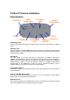


2.4 Box IP Camera Installation
Connections:
Audio Output Jack
Audio-out Jack allows this device to output audio for two-way communication or alerting
sound.
DC Power Jack
The input power is 12VDC. Note that supply the power to the Camera with the power
adapter included in package. Otherwise, the improper power adapter may damage the
unit and result in danger.
LAN Socket
The LAN socket is a RJ-45 connector for connections to 10Base-T Ethernet or
100Base-TX Fast Ethernet cabling. This Ethernet port built N-Way protocol can detect or
negotiate the transmission speed of the network automatically. Please use Category 5
“straight through” cable to connect the Network Camera to a 100Mbps Fast Ethernet
network switch or hub. Note that, in case you need to connect the device to PC or
notebook directly, you should use “cross-over” cable instead.
Factory Default Reset
This button is hidden in the pinhole. Please refer to the Appendix A in this manual for
more information.
Power & LAN LED (green color)
This LED is used to indicate whether DC power is on or not. In addition, this LED will be
flashing while network accessing via Ethernet.
DI/DO Connector
The Camera provides a terminal block with 4 pins of connectors for DI and DO. Please
refer to the Appendix B in this manual for more information.
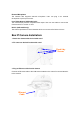
LAN Socket
DC Power
Jack
Factory
Default Reset
Power &
LAN LED
Audio
Output Jack
External MIC
Jack
DI/DO
Connector
Video Out
DC Iris