LNP-0500 series 5-port Industrial PoE+ Unmanaged Ethernet Switches 4*10/100Tx (30W/Port) + 1*10/100Tx User Manual
FCC Warning This Equipment has been tested and found to comply with the limits for a Class-A digital device, pursuant to Part 15 of the FCC rules. These limits are designed to provide reasonable protection against harmful interference in a residential installation. This equipment generates, uses, and can radiate radio frequency energy. It may cause harmful interference to radio communications if the equipment is not installed and used in accordance with the instructions.
Content Introduction ................................................................ 1 Features ................................................................... 1 Package Contents .................................................... 2 Hardware Description ............................................... 3 Physical Dimension .................................................. 3 Front Panel .............................................................. 4 Top View ............................................
Introduction Antaira’s LNP-0500 series switches are smart 5-port Industrial Unmanaged Ethernet Switches supporting IEEE-802.3at compliant (Power-over-Ethernet Plus) on ports 1 to 4. The switches are classified as power source equipment (PSE), and when used in this way, the LNP-0500 series switches enable centralization of the power supply and provide up to 30 watts of power per port. The switches can be used to power IEEE 802.3af or 802.
Package Contents Please refer to the package contents list below. LNP-0500 series - 5-Port Industrial PoE+ Unmanaged Ethernet Switch w/DIN Rail Bracket User Manual Removable Terminal Block Wall-mount Kit (2 Wall-mount Plates with Screws) Compare the contents of the industrial switch with the checklist above. If any item is damaged or missing, please contact Antaira or Antaira’s authorized channel partners for service.
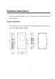
Hardware Description The Industrial switch’s hardware spec, port, cabling information, and wiring installation will be described.
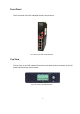
Front Panel The Front Panel of the PoE Industrial Switch is shown below: Front Panel of the PoE Industrial Switch Top View The top view of the PoE Industrial Switch has one terminal block connector of two DC power inputs and relay circuit contact.
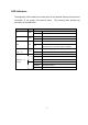
LED Indicators The diagnostic LEDs located on the front panel of the industrial switch provide real-time information of the system and optional status. The following table provides the description of the LED status.
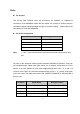
Ports RJ-45 ports The (RJ-45) Fast Ethernet ports will auto-sense for 10Base-T or 100Base-TX connections. Auto MDI/MDIX means that the switch can connect to another switch or workstation without changing straight through or crossover cabling. Please refer to the table below for RJ-45 pin assignment. RJ-45 Pin Assignments Note Pin Number Assignment 1 Rx+ 2 Rx- 3 Tx+ 6 Tx- “+” and “-” signs represent the polarity of the wires that make up each wire pair.
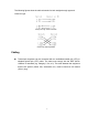
The following figures show the cable schematic for both straight-through type and crossover type. Straight Through Cable Schematic Cross Over Cable Schematic Cabling Twisted-pair segments can be connected with an unshielded twisted pair (UTP) or shielded twisted pair (STP) cable. The cable must comply with the IEEE 802.3u 100Base TX standard (e.g. Category 5, 5e, or 6). The cable between the equipment and the link partner (switch, hub, workstation, etc.) must be less than 100 meters (328 ft.) long.
Wiring the Power Inputs Please follow the steps below to insert the power wire. Insert the positive and negative wires into the PWR1 (V1+, V1-) and PWR2 (V2+,V2-) contacts on the terminal block connector. Tighten the wire-clamp screws to prevent the wires from loosening. Note Use Copper Conductors Only, 60/75°C, Tighten to 5 lb in The wire gauge for the terminal block should range between 12 ~ 18 AWG.
Wiring the Fault Alarm Contact The fault alarm contact is in the middle of the terminal block connector as the picture shows below. By inserting the wires, it will detect the fault status including power failure or port link failure (managed industrial switch only) and form a normally open circuit. An application example for the fault alarm contact is shown as below: Note Use Copper Conductors Only, 60/75°C, Tighten to 5 lb in The wire gauge for the terminal block should range between 12 ~ 24 AWG.
Mounting Installation DIN-Rail Mounting The DIN-Rail is screwed on the industrial switch from the factory. If the DIN-Rail is not screwed on the industrial switch, please see the following pictures to screw the DIN-Rail on the switch. Follow the steps below to hang the industrial switch. 1. Use the screws to screw the DIN-Rail bracket on the rear side of the industrial switch. 2. To remove the DIN-Rail bracket, reverse the step 1. 3.
DIN-Rail on to the track. 4. Then, lightly pull down the bracket on to the rail. 5. Check if the bracket is mounted tight on the rail. 6. To remove the industrial switch from the rail, reverse steps above.
Wall Mounting Follow the steps below to mount the industrial switch using the wall mount bracket. 1. Remove the DIN-Rail bracket from the industrial switch; loosen the screws to remove the DIN-Rail. 2. Place the wall mount bracket on the top and bottom of the industrial switch. 3. Use the screws to screw the wall mount bracket on the industrial switch. 4. Use the hook holes at the corners of the wall mount bracket to hang the industrial switch on the wall. 5.
Hardware Installation This section is to explain how to install the LNP-0500 series Industrial PoE+ Unmanaged Ethernet Switch. Installation Steps 1. Unpack the Industrial switch packing. 2. Check if the DIN-Rail bracket is screwed on the Industrial switch. If the DIN-Rail is not screwed on the Industrial switch, please refer to the DIN-Rail Mounting section for DIN-Rail installation.
Network Application This segment provides an example of an industrial switch application.
Troubleshooting Verify the right power cord/adapter, never use power supply/adapter with noncompliant DC output voltage, or it will burn the equipment. Select the proper UTP/STP cable to construct the network with using the right cable. Use unshielded twisted-pair (UTP) or shield twisted-pair (STP) cable for RJ-45 connections: 100Ω Category 5e/above cable for 10M/100Mbps. Also be sure that the length of any twisted-pair connection does not exceed 100 meters (328 feet).
Technical Specification The LNP-0500 series - 5-Port Industrial PoE+ Unmanaged Ethernet Switch technical specifications is shown below. IEEE 802.3 10Base-T Ethernet Standard IEEE 802.3u 100Base-TX Fast Ethernet IEEE802.3x Flow Control and Back Pressure IEEE802.
Max Power 110 Watts @ 48V, 130 Watts @ 51-55V Consumption Full Load with PoE Function Installation DIN Rail Mounting, Wall Mounting Operating Temp. Operating Humidity Storage Temperature Case Dimension Standard Operating Temperature: -10oC to 70oC Wide Temperature model: -40oC to 75oC 5% to 95% (Non-Condensing) -40oC to 85oC IP-30, 30mm (W) x 99mm (D) x 142mm (H) FCC Class A EMI CE EN61000-4-2/3/4/5/6/8 CE EN61000-6-2 CE EN61000-6-4 Safety UL 508, UL Class 1 Division 2, ISA 12.12.