P193 USER’S MANUAL
TABLE OF CONTENTS INTRODUCTION 1.1 Case Specifications.…..…………………………………………………………………………………..3 1.2 Diagram…………………………………………………………………….…………………………………. 3 HARDWARE INSTALLATION GUIDE 2.1 Setting Up….…………………………………………………………………………………………………. 4 2.2 Power Supply Installation……………………………………………………………………………… 4 2.3 CP Series Power Supply Mount…………………………………………………………………….. 5 2.4 Cable Management………………………………………………………………………………………. 5 2.5 Motherboard Installation..……………………………………………………………………………. 5 2.6 Internal 3.
P193 USER’S MANUAL At Antec, we continually refine and improve our products to ensure the highest quality. It’s possible that your new case will differ slightly from the descriptions in this manual. As of the date of publication, all features, descriptions, and illustrations in this manual are correct. Disclaimer This manual is intended only as a guide for Antec’s computer enclosures.
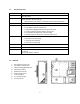
1.1 CASE SPECIFICATIONS Case Type Advanced Mid Tower Color Gunmetal Gray 514mm (H) x 205mm (W) x 590mm (D) 20.25" (H) x 8.1" (W) x 23.25" (D) * Actual clearance for width is 9.5”/241mm due to the side panel fan 35.8 lbs / 16.
HARDWARE INSTALLATION GUIDE 2.1 SETTING UP 1. 2. 3. Place the case upright on a flat, stable surface with the rear of the case facing you. Remove the thumbscrews from the right side panel. Grip the panel at the top and bottom and slide it toward you to open the case. Remove the screws from the left side panel. Grip the panel at the top and bottom and slide it toward you to remove the left side panel. Note: Do not use your fingernails to pry or lift the panels.
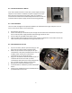
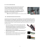
2.3 CP SERIES POWER SUPPLY MOUNT Your Antec P193 enclosure comes with a power supply mounting adapter to mount either a standard-size power supply or the unique Antec CP Series high-performance power supply. This adapter is mounted to the chassis with standard Phillips-head screws. In order to install the CP Series power supply, remove the mounting plate first. 2.4 CABLE ORGANIZERS There is a cable management compartment between the motherboard and right side panel.
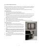
2.6 INTERNAL 3.5” DEVICE INSTALLATION With the front bezel facing you, swing the front door open. It can swing 270º so the door is parallel with the side of the case. You can see there are four 5.25” and one 3.5” external drive bays. Inside the case there are two 3.5” drive cages, which can house up to six hard drives. Note: We recommend using the lower HDD cage to maximize cooling and quiet computing. Upper HDD Installation 1. Remove the thumbscrew holding the upper HDD cage. 2.
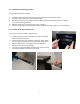
2.7 EXTERNAL 3.5” DEVICE INSTALLATION There is one external 3.5” drive bay. 1. 2. 3. 4. 5. Carefully remove the plastic drive bay cover and metal plate covering the drive bay. Find a pair of 3.5”drive rails in the hardware kit box. Mount the drive rails onto the sides of the 3.5” device. Make sure the metal portion is angled on the outside and facing forward. Slide the device into the drive bay until it clicks into place.
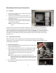
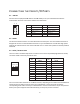
CONNECTING THE FRONT I/O PORTS 3.1 USB 2.0 Connect the front I/O panel USB cable to the USB header pin on your motherboard. Check the motherboard manual to ensure that it matches the table below: 1 2 Pin 9 10 3.
3.4 SWITCH AND LED CONNECTORS Connected to your front panel are LED and switch leads for power, reset, and HDD LED activity. Attach these to the corresponding connectors on your motherboard. Consult your motherboard manual for specific pin header locations. For LEDs, colored wires are positive ( + ). White or black wires are negative ( – ). If the LED does not light up when the system is powered on, try reversing the connection.
COOLING SYSTEM 4.1 TRICOOL™ FANS Rear / Top TriCool™ Fans – There is one rear 120mm and two top 140mm TriCool™ fans pre-installed in the case. They have external, three-speed switches that let you choose between quiet, performance, or maximum cooling on each of the fans. The default speed setting is Low. The two fans are mounted so that the air is exhausting from the case. There are externally accessible switches for these fans located at the top rear of your case.
Side Panel TriCool™ Fan – This Big Boy 200™ fan is placed in the side panel of the case, ensuring proper cooling of the hottest graphics cards and motherboard equipment. Big Boy 200™ Specifications: Size: 200 x 30mm Rated Voltage: DC 12V Operating Voltage: 10.2V ~ 13.8V Speed (RPM) Input Current Air Flow Static Pressure Acoustic Noise Input Power High 800 0.3A (Max.) 3.8 m³ / min (134 CFM) 0.7mm-H2O (0.03 inch-H2O) 29 dBA 3.6W Medium 600 0.17A 3.1 m³ / min (108 CFM) 0.4mm-H2O (0.
Note: In order to build a quieter system we recommend NOT installing the optional fans if they are not necessary for the cooling of your components. If you choose to install them, we recommend using Antec 120mm TriCool™ fans and setting the speed to Low. 4.3 WASHABLE AIR FILTERS There are two filters located behind the front grills and one behind the grill of the side Big Boy 200™.
Antec, Inc. 47900 Fremont Blvd. Fremont, CA 94538 USA tel: 510-770-1200 fax: 510-770-1288 Antec Europe B.V. Stuttgartstraat 12 3047 AS Rotterdam Netherlands tel: +31 (0) 10 462-2060 fax: +31 (0) 10 437-1752 Customer Support: US & Canada 1-800-22ANTEC customersupport@antec.com Europe +31 (0) 10 462-2060 europe.techsupport@antec.com www.antec.com © Copyright 2009 Antec, Inc. All rights reserved. All trademarks are the property of their respective owners.