DF-30 DARK FLEET THE ADVANCED GAMING FORCE USER MANUAL
DF-30 USER’S MANUAL Congratulations on your purchase of the Antec Dark Fleet DF-30. Meet the swifter, lighter Dark Fleet enclosure with the heavyweight feature set: the Dark Fleet DF-30. Up front sit two Fleet-Release™ access doors with tool-free washable fan filters, allowing rapid access to a massive array of drive bays – enough room for 11 total drives.
TABLE OF CONTENTS SECTION 1: INTRODUCTION 1.1 1.2 1.3 1.4 Getting to know your case…………………………………………………. Case specifications…………………………………………………………. Before you begin…………………………………………………………… Locating and positioning your computer…………………………………... 5 6 7 8 SECTION 2: HARDWARE INSTALLATION 2.1 2.2 2.3 2.4 2.5 2.6 2.7 2.8 2.9 Setting up…………………………………………………………………... 10 Motherboard installation…………………………………………………… 12 Standard ATX power supply installation…………………………………... 14 Cable management………………………………………………………….
SECTION 1 4 INTRODUCTION
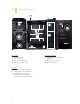
1.1 GETTING TO KNOW YOUR CASE 5 4 10 1 6 8 2 7 7 9 Drive bays 1 5.25” drive bays 2 3.5” drive bays 3 2.5” internal SSD bay 4 2.
1.2 CASE SPECIFICATIONS CASE TYPE Mid Tower COLOR Matte black DIMENSIONS 19.1″ (H) x 7.8″ (W) x 19.1″ (D) 485 mm (H) x 198 mm (W) x 486 mm (D) 15.1 lbs / 6.9 kg 1 x top 140 mm TwoCool™ fan 1 x rear white 120 mm TwoCool™ black-bladed fans with blue LED 2 x front variable-speed 120 mm black -bladed LED fans with blue LED 1 x side 120 mm fan for graphics cards (optional) WEIGHT COOLING DRIVE BAYS 6 ″ ″ 6 x internal 3.5 3 x external 5.25 1 x top external 2.
BEFORE YOU BEGIN 1.3 In order to ensure that your building experience with the Dark Fleet DF-30 will be a positive one, please take note of the following: 7 • While working inside your Dark Fleet DF-30, keep your case on a flat, stable surface. Make sure your build area is clean, well-lit, and free of dust. • Antec cases feature rounded edges that minimize the occurrence of hand injuries. Nonetheless, exercise caution and control when handling case interiors.
1.4 LOCATING AND POSITIONING YOUR COMPUTER Your DF-30 has backwards- and top-facing exhaust fans, as well as front-mounted intake fans and one sidemounted front air intake. For optimum performance, we recommend leaving the front air intakes unobstructed. When open, the DF-30’s Fleet-Release™ doors take up an additional 15.5 cm of space in the front.
SECTION 2 9 HARDWARE INSTALLATION
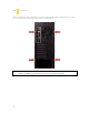
2.1 SETTING UP Put the case upright on a flat, stable surface so that the rear panel (power supply and expansion slots) is facing you. To remove the left and right side panels, remove these thumbscrews: Note: Place the panel thumbscrews aside carefully and remember where they are – they look very similar to the HDD cage thumbscrews, but they are NOT interchangeable.
Now rest your case with the left side up. Here’s what we’ll be working with first: E D B C A A – Power supply mounts B – 5.25” drive bay area C – 3.5” drive bay area D – Front panel wiring E – I/O panel Note: Do not use your fingernails to pry or lift the panels. Damage to the panels or injury to your fingernails may result. Note: This manual is not designed to cover CPU, RAM, or expansion card installation. Please consult your motherboard manual for specific mounting instructions and troubleshooting.
MOTHERBOARD INSTALLATION 2.2 Before proceeding: - Check the manual for your CPU cooler to find out if there are steps you must do before installing the motherboard Make sure you have the correct I/O panel for your motherboard. If the panel provided with the case isn’t suitable, please contact your motherboard manufacturer for the correct I/O panel. Make sure you have the correct I/O panel. This mismatched I/O panel can cause difficulties down the road. 1.
3. Now remove your motherboard by lifting it up. Lift your motherboard out to install the standoffs. 4. Install standoffs as needed and put the motherboard back in. 5. Screw in your motherboard to the standoffs with the provided Phillips-head screws. Caution: Make sure to remove any unused motherboard standoffs. They may come into contact with the back of the motherboard and may electrify your case exterior if left connected.
Note: The DF-30 comes with a CPU cutout on the motherboard tray, which will allow you to change your CPU heatsink without removing the motherboard. STANDARD ATX POWER SUPPLY INSTALLATION 2.3 The DF-30 can accommodate a standard-size ATX power supply. 1. With the case upright, place the power supply on the bottom of the case. PSU resting on the standard PSU mount. 14 2. Push the power supply to the back of the case and align the mounting holes. 3.
Use these screws to secure your power supply to the case. Note: Power supplies with fans on the bottom of the power supply will need to be mounted so that the fan is facing the top of the case. The DF-30 provides mounting holes for power supplies with standard mounting layouts to be installed right side up or upside down. CABLE MANAGEMENT 2.4 There is a cable management compartment behind the 3.5” drive cage. You can tuck or route excess cables in this compartment. 15 1.
INTERNAL 3.5” DEVICE INSTALLATION 2.5 The DF-30 includes two Fleet-Release™ access doors. With the front bezel facing you, they are located by default on the bottom nine drive bay slots (each door covers three drive bays). 1. Open the Fleet-ReleaseTM access door. Opening the Fleet-Release™ access door by gently pressing the left side to release it, and then swing it open. 2. 16 Insert your 3.5” device into the 3.5” drive cage from the front of the case.
Installing a 3.5” internal device 3. Fasten the device in place with the provided screws on both side of the drive cage. Make sure to install screws on the left side… 17 …as well as the right side. 4. Mount any other 3.5” HDD devices accordingly. 5. Connect the appropriate power and data cables to the device(s), using cable routing as desired. 6. Close the Fleet-Release™ access door.
EXTERNAL 3.5” DEVICE INSTALLATION 2.6 There is one external 3.5” drive bay under the 5.25” drive bays. Remove this drive bay cover. 1. Carefully remove the 3.5” drive bay cover from the bezel. Load the drives from the front, lining them up to the front of the drive cage. Insert your drive as shown. 18 2. With one hand supporting the drive, fasten the drive with the screws provided. 3.
USING THE TOP 2.5” HOT-SWAP BAY 2.7 The DF-30’s top 2.5” hard drive bay is hot-swap capable. To use the hot-swap feature, ensure that your motherboard is configured for hot-swap. Make sure to install all related drivers that come with your motherboard and turn on the AHCI function in the BIOS to activate the hot swap feature. Using the top 2.5” hot-swap drive bay A. LOADING: 1. Align your SATA HDD with the drive bay with the connector facing the case. 2.
EXTERNAL 5.25” DEVICE INSTALLATION 2.8 There are three externally accessible 5.25” drive bays. Before you begin, remove both side panels. 1. First, remove the drive bay faceplate and metal cover plate as shown below. The plastic drive bay faceplate should pop free. A screwdriver may be needed to remove the metal cover plate. 2. Slide your 5.25” device into the bay from the front of the case. 5.25” device installation 20 3.
INTERNAL 2. 5” DEVICE INSTALLATION 2.9 There is a 2.5” device mounting location located at the bottom of the case. To use this mounting location: 1. Locate the bay at the bottom of the case. The 2.5” mounting location 2. Using the screws provided, secure your 2.5” device. Secure your 2.5” device from the bottom.
3.
USB 2.0 3.1 Connect the front I/O panel USB cable to the USB header pin on your motherboard. Check your motherboard user’s manual to ensure that it matches the table below: 1 2 Pin Signal Names Pin Signal Names 1 USB Power 1 Negative Signal 1 Positive Signal 1 Ground 1 Key (No Connection) 2 USB Power 2 Negative Signal 2 Positive Signal 2 Ground 2 Empty Pin 3 5 7 9 9 3.
POWER SWITCH / RESET SWITCH / HARD DISK DRIVE LED CONNECTORS 3.3 Connected to your front panel are LED and switch leads for power, reset, and HDD LED activity. Attach these to the corresponding connectors on your motherboard. Consult your motherboard manual for specific pin header locations. For LEDs, colored wires are positive ( + ). White or black wires are negative ( – ). If the LED does not light up when the system is powered on, try reversing the connection.
SECTION 4 25 COOLING SYSTEM
4.
4.2 TOP 140 MM TWOCOOL™ FAN The DF-30 comes with one 140mm TwoCool™ LED fan. This fan has a two-speed switch that lets you choose the speed best suited to your need and a switch to turn on or off the LED. These switches are located at the rear of the case. The default fan speed setting is Low. 140 MM FAN SPECIFICATIONS: Size: Rated Voltage: Operating Voltage: Speed High 1200RPM Low 800RPM 4.3 140 x 25 mm two-speed fan 12V DC 10.8V ~ 13.2 V Input Current 0.3A 0.2A Air Flow Static Pressure 1.
4.4 REAR EXHAUST 120 MM TWOCOOL™ FANS There is one 120 x 25 mm TwoCool™ blue LED fan preinstalled at the rear of the case. This fan is designed to pull hot air out of the case. Each fan comes with two-speed switch that let you choose the speed best suited to your need. These switches are located at the rear of the case. The default fan speed setting is Low.
4.6 WASHABLE AIR FILTERS There is a filter located behind the faceplate of each Fleet-ReleaseTM Access Doors. There are total of three front air filters that come with the case. Removing the washable air filter. Note the filter tabs. To clean the filter: 1. Open the Fleet-ReleaseTM Access Doors. Locate the filter tab behind the faceplate. 2. Note: 29 Lift the tab right and pull it upwards to remove the filter. See picture. From time to time it will be necessary to wash the installed air filter.
Antec, Inc. 47900 Fremont Blvd. Fremont, CA 94538 tel: 510-770-1200 fax: 510-770-1288 Antec Europe B.V. Stuttgartstraat 12 3047 AS Rotterdam The Netherlands tel: +31 (0) 10 462-2060 fax: +31 (0) 10 437-1752 Technical Support: US & Canada 1-800-22ANTEC customersupport@antec.com Europe +31 (0) 10 462-2060 europe.techsupport@antec.com www.antec.com © Copyright 2010 Antec, Inc. All rights reserved. All trademarks are the property of their respective owners.