
User Manual


17
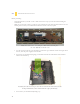
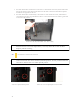
3. For cables which will be routed back to front drives or other internal accessories, feed the cables back
through the insertion point nearest the destination of the cable. Connect the cable and then pull the
slack back to the right side of the case.
4. For cables which will be routed directly to front drives or other internal accessories, cable tiedowns
are located along the drive cage. Bundle front drives’ or other internal accessories’ cables together and
secure them using tiedowns.
Tiedown locations for front drive bay cable routing
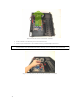
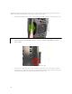
2.6 INTERNAL 3.5” DEVICE INSTALLATION
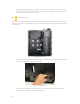
Lock lever in default, unlocked position. Slide the lever to its most upward point to lock access doors.
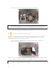
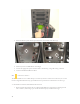
Note: If you plan to use the Fleet-Swap feature, you should leave one or two cables with four
SATA connectors in the main compartment, so that they will be able to reach the Fleet-
Swap bay without stretching.
Note: The DF-85 contains a Fleet-Release™ access door lock lever on the left side panel. DF-85
comes with the lock lever in the downward, unlocked position. To lock your Fleet-Release™
access doors, slide the lever to its fullest upward position.