SOLO II SILENCE RENEWED USER MANUAL
SOLO II USER’S MANUAL Congratulations on your purchase of the Antec SOLO II. The SOLO II emphasizes Quiet Computing™ and reinvents Antec’s renowned Sonata line with a new set of attractive, practical features. Externally, the SOLO II’s dual-layer 1.0 mm SECC / polycarbonate top & side panels absorb noise for exceptional sound dampening.
TABLE OF CONTENTS SECTION 1: INTRODUCTION 1.1 1.2 1.3 1.4 Getting to Know your Chassis ..................................................................5 Chassis Specifications...............................................................................6 Included Screws .......................................................................................6 Before you Begin ......................................................................................7 SECTION 2: HARDWARE INSTALLATION 2.1 2.
SECTION 1 4 INTRODUCTION
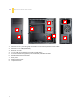
1.1 GETTING TO KNOW YOUR CHASSIS 8 3 4 6 1 5 8 1. 2. 3. 4. 5. 6. 7. 8. 9. 5 7 2 Internal: 3 x 3.5” / 2.5”using tray mount OR 2 x 3.5” with suspension mount cables Internal: 1 x 2.5” SSD (dedicated) External: 2 x 5.
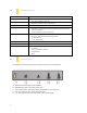
CHASSIS SPECIFICATIONS 1.2 Chassis Type Mid Tower Chassis Color Piano Black Dimensions 17.3” (H) x 8.1” (W) x 18.5” (D) 440 mm (H) x 205 mm (W) x 470 mm (D) Weight 20.2 lbs / 9.1 kg Cooling - Drive Bays - Rear 120 mm TrueQuiet™ fan with preinstalled silicone grommets and 2-speed switch 2 front 120 mm fan mounts (optional) 3 x 3.5”/2.5” using tray mounts with preinstalled silicone grommets OR 2 x 3.5” with suspension mounting system 2 x external 5.25” 1 x 2.
BEFORE YOU BEGIN 1.4 In order to ensure that your building experience with the SOLO II will be a positive one, please take note of the following: 7 • While working inside your SOLO II, keep your chassis on a flat, stable surface. Make sure your build environment is clean, well-lit, and free of dust. • Antec chassis feature rounded edges that minimize the occurrence of hand injuries. Nonetheless, exercise caution and control when handling chassis interiors.
SECTION 2 8 HARDWARE INSTALLATION
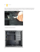
2.1 SETTING UP Begin by removing the left side panel by loosening the thumbscrews and swinging the panel outward, pulling it back towards you; this will completely remove it. Cut the ties on the 5.25” drive cage with a wire cutter and remove the plastic bag of screws. The SOLO II should now look like this.
2.2 MOTHERBOARD INSTALLATION Before proceeding: Check the manual for your CPU cooler to find out if there are steps you must do before installing the motherboard. Make sure you have the correct I/O panel for your motherboard. If the panel provided with the chassis isn’t suitable, please contact your motherboard manufacturer for the correct I/O panel. Make sure you have the correct I/O panel. The SOLO II comes with four preinstalled motherboard standoffs.
3. Screw your motherboard into the standoffs with the provided motherboard mounting screws. 2.3 INSTALLING THE KUHLER H2O The following instructs how to install the Antec KUHLER H2O liquid CPU cooler (620 / 920). For any other CPU coolers, please consult your manufacturer’s installation guide. - Caution: We strongly recommend installing the KUHLER H2O only after installing the power supply (See Step 2.4). PSU installation will be difficult otherwise.
2. The TrueQuiet™ fan has two small black clips attached to the fan’s two-speed switch. With your thumb and forefinger, spread the clips while pushing from the rear of the case to remove the switch. 3. Preparing the KUHLER H2O backplate is specific to your CPU socket. Please refer to the KUHLER H2O installation guide, available at http://www.antec.com/Believe_it/product.php?id=Mjc2OCYxNw== (KUHLER H2O 620) or http://www.antec.com/Believe_it/product.php?id=NzA0MzcwJjE3 (KUHLER H2O 920) for more information.
2. Remove the second screw with your other hand supporting the beam so the beam won’t drop. 3. Repeat steps 1 and 2 for the support beam screws at the rear of the case. . 4. Place the SOLO II on its side. Position the PSU into the mount and secure it with the PSU screws provided. If your PSU has a fan on its top side, make sure it aligns with the SOLO II’s top intake vent. 5. Re-attach the PSU support beam.
2.5 CABLE MANAGEMENT There is a cable management area between the motherboard and right side panel as well as cable hooks located on the side of the 3.5” drive cage. You can tuck excess cables in this area or route them to the drive bays. Choose the cables you would like to pass through the holes behind the motherboard tray. Pull them through the hole toward the right side of the case.
2. Attach the drive rails to your 5.25” device. These rails have three depth settings that accommodate the depth of your 5.25” drive. 3. Make sure to properly align your drive rails with your 5.25” drive. We recommend attaching one rail with one of the 5.25” drive screws and closing the bezel as a trial. Use the four 5.25” drive screws to secure your drive. 4. Slide the 5.25” drive into the appropriate drive bay. You will know the drive is secure when you hear a “click.” 5. Mount any other 5.
2.7 INTERNAL 3.5” AND 2.5” INSTALLATION (TRAY MOUNTS AND SUSPENSION MOUNTING SYSTEM) The following text outlines the preparatory stages for installing 3.5” / 2.5” drives using drives trays and the suspension mounting system. 1. If you have reattached it, remove the left side panel. Loosen the side panel screws and swing the panel outward, pulling it back towards you; this will completely remove it. 2. Remove the front bezel by locating the bezel tabs and pulling them to release the bezel .
3.5” drive 2.5” drive 5. Insert the 3.5” / 2.5” drive into the drive cage by pinching the ends of the drive tray and sliding the tray along the rails until the tray locks firmly into position. 3.5” drive 2.5” drive 6. Mount any other 3.5” / 2.5” devices accordingly. For Suspension Mounting Installation: The SOLO II accommodates two 3.5” drives using the suspension mounting system. Each hard drive needs two suspenders (front and rear) to mount.
4. Twist the rear suspender and guide the hard drive through it. 5. Find the appropriate power connector on the PSU and connect it to the device. 6. Repeat the same procedure for a second drive if necessary. 7. Close and secure the drive cage door. 2.8 INTERNAL 2.5” DEVICE INSTALLATION Toward the bottom-right of the motherboard tray, you will see a mount for a 2.5” device. To install a 2.5” device: 1. Align the 2.5” drive with the mounting holes with the back of the drive facing the back of the chassis.
SECTION 3 19 FRONT I/O PORTS
USB 2.0 3.1 Connect the front I/O panel USB cable to the USB header pin on your motherboard. Check your motherboard user’s manual to ensure that it matches the table below: 1 2 9 10 3.2 Pin SignalNames Pin SignalNames 1 USBPower1 2 USBPower2 3 NegativeSignal1 4 NegativeSignal2 5 PositiveSignal1 6 PositiveSignal2 7 Ground1 8 Ground2 9 Key(NoConnection) 10 EmptyPin USB 3.0 The SOLO II comes with two front panel USB 3.0 ports and includes an internal motherboard connector.
3.3 AC’97 / HD AUDIOPORTS There is an Intel® standard 10-pin AC’97 connector and an Intel® 10-pin HDA (High Definition Audio) connectorlinked to the front panel of the chassis.
3.5 REWIRING MOTHERBOARD HEADER CONNECTIONS There may come a time when you need to reconfigure the pin-out of a motherboard header connector. Examples could be for your USB header, audio input header, or some other front panel connector such as the Power Button connector. Before performing any work, please refer to your motherboard user’s manual or your motherboard manufacturer's website to confirm the pin-out needed for your connector.
SECTION 4 23 COOLING SYSTEM
INCLUDED 120 MM TRUEQUIET™ REAR FAN 4.1 The SOLO II comes with a 120 mm TrueQuiet™ rear fan. This fan has a two-speed switch that lets you choose the speed best suited to your need. The switch is located at the rear of the case. The default fan speed setting is Low. 120 mm Fan Specifications: Size: Rated Voltage: Operating Voltage: Speed High 1000RPM Low 600RPM Note: 4.2 Input Current 0.12A 0.06A 120 x 25mm two-speed fan 12V DC 10.8V ~ 13.2 V Air Flow 1.0m³ / min (35.8 CFM) 0.6m³ / min (21.
4.3 OPTIONAL FANS The SOLO II can accommodate two 120 mm front intake fans. The following shows you how to install one of thesefans using a 120 mm TrueQuiet™ fan: 1. Remove the fan filter as depicted in section 4.2. 2. Insert the mounting pin through the mounting hole tail-first. Pull the tail through the hole and push the pin through with the head of the pin. Apply a firm, consistent force, but do not yank the pin through. 3.
Antec, Inc. 47900 Fremont Blvd. Fremont, CA94538 tel: 510-770-1200 fax: 510-770-1288 Antec Europe B.V. Stuttgartstraat 12 3047 AS Rotterdam The Netherlands tel: +49-40-226139-22 fax: +31 (0) 10 437-1752 Technical Support: US &Canada 1-800-22ANTEC customersupport@antec.com Europe +31 (0) 10 462-2060 europe.techsupport@antec.com www.antec.com © Copyright 2011 Antec, Inc. All rights reserved. All trademarks are the property of their respective owners.