SONATA III USER’S MANUAL
1 TABLE OF CONTENTS SECTION 1: INTRODUCTION 1.1 Getting to Know Your Case…………………………………………………………………………………. 3 1.2 Case Specifications……………………………………………………………………………………………… 5 1.3 Parts Included…………………………………………………………………………………………………….. 5 1.4 Before You Begin………………………………………………………………………………………………… 6 2.1 Locating and Positioning Your Computer……………………………………………………………. 7 SECTION 2: INSTALLING HARDWARE 2.4 Removing the Side Panel…………………………………………………………………………………….. 7 2.2 Cable Management…………………………………………………………………………………………….
2 SONATA III 500 USER’S MANUAL Congratulations on your purchase of the Antec Sonata III 500! Your Sonata III 500 is designed to be the quietest, easiest-to-use case on the market. The Sonata III 500 is powered by EA-500D Green power supply unit equipped with Universal Input and Active PFC, which allows you to connect your power supply to any AC power outlet between 100V and 240V as well as reducing electrical waste. At Antec, we continually refine and improve our products to ensure the highest quality.
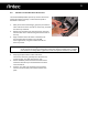
3 INTRODUCTION 1.1 GETTING TO KNOW YOUR CASE 1. 120mm rear TriCool™ fan Positioned at the rear of your case. Draws warm air through the interior of the case and out the back. See Section 4.1 for more detail. 2. 120mm front fan mount A fan mounting location is provided for mounting fans up to 120mm in size. See Section 4.2 for more detail. 3. Washable air filter This filters out dust from the air entering your computer case. For removal and washing instructions, see Section 4.3. 4.
4 6 7 5 1 8 9 2 10 4 3
5 1.2 CASE SPECIFICATIONS Case Type Mid Tower Color Gloss Black 19.5 " (H) x 10.5" (W) x 21.5" (D) 495mm (H) x 266.7mm (W) x 495mm (D) 9.1kg / 20.2 lbs Dimensions Weight Cooling 1 x Rear 120mm TriCool™ LED fan 1 x Front 120mm fan mount (optional) Drive Bays 10 Drive Bays: - 3 x External 5.25” drive bays - 2 x Internal 3.5” drive bays - 4 x Internal 3.5” drive bays Expansion Slots 7 Motherboard Size Mini-ITX, microATX, Standard ATX 2 x USB 2.
6 1.4 BEFORE YOU BEGIN In order to ensure that your building experience with the Sonata III 500 will be a positive one, please take note of the following: • While working inside your Sonata III 500, keep your case on a flat, stable surface. Keep a clean, dust-free environment for building your computer. • Antec case interiors feature rounded edges that minimize the occurrence of hand injuries. Nonetheless, we strongly recommend taking the appropriate time and care when working inside the case.
7 1.5 LOCATING AND POSITIONING YOUR COMPUTER Your Antec Sonata III 500 has a backwards-facing exhaust fan and two air intakes on the sides of the front panel. For optimum performance, we recommend leaving the front air intakes unobstructed. The Sonata III 500 can operate resting sideways as well as vertically. Do not rest the Sonata III 500 upside down, as this will impede operation of optical drives. SECTION 2: HARDWARE INSTALLATION GUIDE 2.1 1.
8 2.2 CABLE MANAGEMENT There is a cable management compartment behind the 3.5” drive cage. You can tuck or route excess cables in this compartment. This will keep the cables from interfering with airflow in your case and help with cooling. 1. 2. 3. 4. Open the side panel as described in section 2.1. Locate the cable management compartment with cable ties located behind the walls of the external 3.5” drive cage. Tuck or route your excess cables to the compartment. Use cable ties to hold them in place. 2.
9 2.4 INTERNAL 3.5” DRIVE BAY DEVICE INSTALLATION The Sonata III 500 provides space for up to four internal 3.5” hard drives. Before you begin, remove the side panel as described in section 2.1. 1. 2. 3. With your thumb and forefinger, grasp the pinch tabs on either side of one of the internal 3.5” drive trays, and slide the drive tray outwards. Mount your hard drive onto the internal 3.5” drive tray with the hard drive’s sockets facing towards the back of the tray.
10 2.5 EXTERNAL 3.5” DRIVE BAY DEVICE INSTALLATION The Sonata III 500 provides space for two external 3.5” devices. Before you begin, remove the side panel as described in section 2.1. 1. 2. 3. 4. 5. 2.6 With your thumb and forefinger, grasp the pinch tabs on either side of one of the external 3.5” drive trays, and slide the drive tray outwards. Remove the screws from the top or bottom panel of the external 3.5” drive tray.
11 SECTION 3: CONNECTING THE FRONT I/O PORTS 3.1 USB 2.0 PORTS Connect the front I/O panel USB cable to the USB header pin on your motherboard. Check the motherboard user’s manual to ensure that it matches the table below: 1 2 9 10 3.
12 3.3 POWER SWITCH / RESET SWITCH / HARD DISK DRIVE LED CONNECTORS Connected to your front panel are LED and switch leads for power, reset, and HDD activity. Attach these to the corresponding connectors on your motherboard. Consult your motherboard manual for specific pin header locations. For LEDs, colored wires are positive ( + ). White or black wires are negative ( – ). If the LED does not light up when the system is powered on, try reversing the connection.
13 SECTION 4: COOLING SYSTEM 4.1 TRICOOL™ FAN Top TriCool™ Fan – The case comes with a 200mm top exhaust blue LED fan. The fan is installed so the air will be blown out of the case. This fan comes with a three-speed switch that let you choose the speed best suited to your need. The default fan speed setting is Low. 120mm TriCool™ Specifications Size: 120 x 25mm TriCool™ fan Rated Voltage: 12V Operating Voltage: 10.2V - 13.
14 4.2 INSTALLING AN ADDITIONAL FAN There is one optional 120mm fan mount located at on the side of the internal 3.5” drive bays. We recommend using Antec 120mm speed control fans and setting the speed to Low. These fans must be installed so that the air is blowing into the case. Front Fan – A front fan can be used to enhance graphics card cooling. The fan should be installed to pull air into the front of the case. To install the front fan, first remove the side panel as described in section 2.1. 1.
15 SECTION 5: COMMONLY ASKED QUESTIONS My case is missing drive rails. Check the back of the 5.25” drive bezel. They should be located there. If you see purple or black, it’s there. My side panel is locked in place. If the side panel appears to be stuck in the locked position, place the case down with the left panel facing up. Push and pull on the lever with gentle, firm pressure and it will come off.
16 header out and use the Reset switch temporarily. If the system boots up, then the power lead switch may be faulty. Please call 1-800-222-6832 and obtain a replacement switch. Do I need more fans to cool my system? In most cases, no, you do not need more fans to cool your system. Please note, however, that the Sonata III 500 was designed for standard usage levels, and extensive addition of high-temperature hardware may adversely affect cooling performance.
17 Antec, Inc. 47900 Fremont Blvd. Fremont, CA 94538 USA tel: 510-770-1200 fax: 510-770-1288 Antec Europe B.V. Stuttgartstraat 12 3047 AS Rotterdam Netherlands tel: +31 (0) 10 462-2060 fax: +31 (0) 10 437-1752 Customer Support: US & Canada 1-800-22ANTEC customersupport@antec.com Europe +31 (0) 10 462-2060 europe.techsupport@antec.com www.antec.com © Copyright 2009 Antec, Inc. All rights reserved. All trademarks are the property of their respective owners.