Three Hundred Two 1 User Manual
Three Hundred Two User Manual Congratulations on your purchase of the Three Hundred Two! The team that brought you the Three Hundred is back with an enclosure designed to handle tomorrow’s high-performance systems. Introducing the Three Hundred Two, the next standard in affordable gaming cases. Our newest chassis is built specifically for gamers, from its attractive, yet functional front bezel, to its advanced cooling system. With tool-less 5.25” & 3.
Table of Contents Section 1: Introduction 1.1 1.2 1.3 Getting to Know Your Chassis ............................................................................5 Chassis Specifications.........................................................................................6 Included Screws .................................................................................................6 Section 2: Hardware Installation 2.1 2.2 2.3 2.4 2.5 2.6 2.7 2.8 2.9 2.10 Setting Up ...................................
Section 1 Introduction Three Hundred Two User Manual 4
1.1 Getting to Know Your Chassis 1. 2. 3. 4. 5. 6. 7. 8. 9. 10. 11. 12. 13. 5 3 x 5.25” drive bays 2 x 2.5” drive bays 6 x 3.5” drive bays 1 x 120 mm rear TwoCool fan (standard) 1 x 140 mm top TwoCool fan (standard) 2 x 120 mm front intake fans (optional) 1 x 120 mm side intake fan (optional) 1 x 120 mm side exhaust fan behind motherboard (optional) 8 expansion slots CPU cutout Motherboard mount: Standard ATX, microATX or Mini-ITX Power supply mount Front ports: 2 x USB 3.
1.2 Chassis Specifications Chassis Type Chassis Color Dimensions Weight Cooling Drive Bays Expansion Slots Motherboard Size Front I/O Panel 1.3 Mid Tower Black 513 mm (H) x 229 mm (W) x 471 mm (D) 20.2” (H) x 9” (W) x 18.5” (D) 15.3 lbs / 6.9 kg - 1 x 140 mm top TwoCool fan (standard) - 1 x 120 mm rear TwoCool fan (standard) - 2 x 120 mm front intake fans (optional) - 1 x 120 mm exhaust fan behind motherboard tray (optional) - 1 x 120 mm side panel fan to cool graphics cards (optional) - 3 x 5.
Section 2 Hardware Installation Three Hundred Two User Manual 7
2.1 Setting Up When working in your case, please keep the following in mind: 2.2 Put the case upright on a flat, stable surface so that the rear panel (power supply and expansion slots) is facing you. Handle all components and cards with care. To avoid electrostatic discharge, ground yourself periodically by touching an unpainted metal surface or by using a wrist grounding strap. Before you connect a cable, ensure that both connectors are correctly aligned and oriented.
2.3 Motherboard Installation Before proceeding, check the manual for your CPU cooler to find out if there are steps you must do before installing the motherboard. Make sure you have the correct I/O panel for your motherboard. If the panel provided with the chassis isn’t suitable, please contact your motherboard manufacturer for the correct I/O panel. Make sure you have the correct I/O panel. This case comes with 4 preinstalled motherboard standoffs.
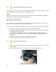
2.4 Installing KUHLER H2O Liquid Coolers The following instructs how to install the Antec KUHLER H2O liquid CPU cooler (620 / 920). For any other CPU coolers, please consult your manufacturer’s installation guide. Caution: Check your motherboard’s CPU socket to ensure its compatibility with the KUHLER H2O. The KUHLER H2O 620 / 920 is compatible with the following CPU sockets: Intel® LGA 1155 / 1156 / 1366 / 2011* AMD® AM2 / AM3 / AM2+ / AM3+ *Your unit may not contain the LGA 2011 mounting bracket.
2.6 External 5.25” Device Installation The Three Hundred Two can support up to three 5.25” devices. 1. Remove the side panels and front bezel as directed in Section 2.2. 2. Remove the drive bay cover by pressing in on the four small tabs on either side of the cover, then push cover out the front of the bezel. 3. Replace the front bezel on the front of the chassis. 4. Slide your 5.25” drive through the front of the chassis until it lines up flush with the front bezel.
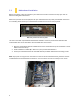
2.7 Internal 2.5” Device Installation There are two 2.5” drive mounting locations in the Three Hundred Two: on the back of the motherboard tray and at the bottom of the case. To install on the back of the motherboard tray: 1. Remove the side panels as described in Section 2.2. 2. Secure your drive with the 2.5” screws provided (C in Section 1.3). Your drive will attach on the back of the motherboard tray, with screws affixing from the front of the tray.
2.8 Internal 3.5” Device Installation The Three Hundred Two includes 6 pairs of 3.5” drive rails. You will need 1 pair per 3.5” drive. 1. Line up the drive rail pins to the sides of your 3.5” drive. Ensure that the squeeze-tabs are aligned on the side of your drive that does not have power or data connectors. 2. Snap the rail into place. 3. Repeat steps 1-2 for the other side of the 3.5” drive. 4. Pinch the ends of the drive rails together and slide the drive into the 3.
2.10 Expansion Slot Device Installation When installing graphics cards or other expansion cards, you must first remove the rear place covering the expansion slots. 1. With the rear of the case facing you, remove the 2 screws shown to remove the plate. 2. Install your expansion cards according to the manufacturer’s instructions. 3. Repalce the plate and screws.
Section 3 Front I/O Ports 15
Three Hundred Two User Manual 3.1 USB 3.0 The Three Hundred Two comes with two front panel USB 3.0 ports and includes an internal motherboard connector. To access USB 3.0 capability from the front panel: 1. Identify the USB 3.0 header on your motherboard. 2. Connect the USB 3.0 header to the motherboard port. Be sure to align the connector in the proper orientation so that you do not damage the pins on your motherboard. Align the connector properly to prevent damage to your motherboard. 3.
3.3 Power Switch / Reset Switch / Hard Disk Drive LED Connectors Connected to your front panel are LED leads for power and HDD activity, as well as switch leads for the power and reset buttons. Attach these to the corresponding connectors on your motherboard. Consult your motherboard manual for specific pin header locations. For LEDs, colored wires are positive ( + ). White or black wires are negative ( – ). If the LED does not light up when the system is powered on, try reversing the connection.
3.4 Rewiring Motherboard Header Connections There may come a time when you need to reconfigure the pin-out of a motherboard header connector. Examples could be for your USB header, audio input header, or some other front panel connector such as the Power Button connector. Before performing any work, please refer to your motherboard user’s manual or your motherboard manufacturer's website to confirm the pin-out needed for your connector.
Section 4 Cooling System Three Hundred Two User Manual 19
4.1 Included Fans The Three Hundred Two comes with two standard fans (yellow outline) – a rear 120 mm TwoCool fan and a top 140 mm TwoCool fan. The red rectangles indicate additional fan mounts. Mounting procedures for these fans is discussed in Section 4.2. 120 mm TwoCool Specifications Size: 120 x 25 mm TwoCool™ fan Rated Voltage: 12V Operating Voltage: 10.8V ~ 13.2V Speed (RPM) Input Current Airflow Static Pressure Acoustic Noise Input Power High 1200 0.20A (Max.) 1.2 m³ / min (42.6 CFM) 0.
4.2 Optional Fans The Three Hundred Two includes mounts for up to four more fans. These mounts are as follows: - 2 x front intake 120 mm mounts 1 x side 120 mm mounts 1 x 120 mm mount behind motherboard Front intake 120 mm fans 1. Remove the front bezel as outlined in Section 2.2. 2. Align the fan with the screw holes and screw in the fan in the top-left and lower-right holes (as pictured). 3. Screw in the long fan screws (D in Section 1.3).
4.3 Air Filters There are two filters in the Three Hundred Two that can be removed and cleaned: the front filter and the PSU intake filter. To remove the front air filter: 1. Remove the front bezel as described in Section 2.2. 2. Orient the bezel by holding it with the inside facing you, with the drive bay covers to the right. 3. Starting from the left side, use your thumbs to push the first two tabs out while using your index fingers to pull the filter away from the bezel. 4.
Antec, Inc. 47900 Fremont Blvd. Fremont, CA94538 tel: 510-770-1200 fax: 510-770-1288 Antec Europe B.V. Stuttgartstraat 12 3047 AS Rotterdam The Netherlands tel: +49-40-226139-22 fax: +31 (0) 10 437-1752 Technical Support US &Canada 1-800-22ANTEC customersupport@antec.com Europe +31 (0) 10 462-2060 europe.techsupport@antec.com www.antec.com © Copyright 2012 Antec, Inc. All rights reserved. All trademarks are the property of their respective owners.