Isochrone OCX-V achieves the breakthrough clock stability by placing the quartz crystal in an isolated, temperature controlled oven. Constant temperature control of the crystal oscillator and a proprietary Jitter Management Module provide unprecedented sonic benefits. Isochrone OCX-V takes the digital sound out of digital audio, giving you the audio in its purest form whether connected to digital mixer, Pro-Tools system, DAW or digital effects unit.
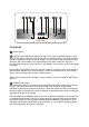
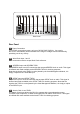
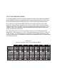
1 2 3 4 5 6 7 8 9 10 Front Panel Front Panel 1 Power Switch 2 SOURCE Knob Designates which input the OCX-V receives its timing reference from. The first five options correspond to physical inputs on the back of the unit. The final setting, OVEN, configures the OCX-V to use its internal, oven controlled crystal oscillator as timing reference, with one exception.
The DA mode will not work if the SOURCE knob is set to VIDEO or OVEN, as there is no audio reference to distribute. In this case the red LED above SAMPLE RATE knob will flash. Note that in the DA mode, the OCX-V can work with non-standard sample rates as may occur in vari-speed mode; any sample rate from 30 to 202 kHz is acceptable. 4 Pull up / Pull down Buttons These buttons are used to modify the outgoing sample rate chosen with the SAMPLE RATE knob.
8 Alternate Sample Rate Selector for Word Clock outputs 7 and 8. Word clock outputs 7 and 8 are capable of outputting frequencies different from the signal on WC 1-6. The first five settings of the switch choose frequencies that are multiples of the output frequency of the audio generator. The final setting, 256 WC, configures the output to generate the 256 FS Clock, a protocol used by some Digidesign components.
9 Word Clock Termination Status LEDs When lit, the corresponding Word Clock output is in use, and is properly Terminated at 75 ohms. Blinking means the corresponding output is over-terminated. Dark means the corresponding output is unused or is not terminated. 10 Video Generator knob This knob selects the video signal provided by the four video outputs on the back of the OCX-V. The first five choices provide different video standards.
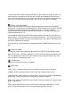
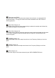
11 12 13 14 15 16 17 18 19 20 21 Rear Panel Rear Panel 11 Power Connection This IES AC connection accepts an input of 95-245 VAC 50/60 Hz. As a result, the OCX-V automatically accommodates to the range of voltages found internationally, permitting use in any country. 12 Word Clock input 1 and 2 BNC connections used to accept Word Clock reference. 13 AES/EBU Input and AES/EBU THRU The AES/EBU Input is an XLR connection that accepts AES/EBU clock or audio.
16 Video input and THRU The video input is a BNC connection that accepts video reference, see appendix B for supported formats. This signal is buffered and made available at the Video THRU for chaining purposes. 17 Word Clock Outputs 1-6 The sample rate provided by these outputs always matches the sample rate indicated by the Frequency Display on the front panel.
OCX-V GEARBOXING MODE In Gearboxing Mode, the OCX-V always generates an output clock at the sample rate set by the SAMPLE RATE knob, regardless of the incoming reference frequency. This output clock is still phase-locked to the reference input, but the sample rates need not match. For example, you may set the SAMPLE RATE knob at 48 kHz and apply a 44.1 kHz reference. The device then "gearboxes" 44.1 kHz into 48 kHz output, as selected by the SAMPLE RATE knob.
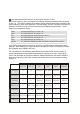
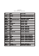
Appendix B Table of valid input video formats