SMARTS BROADCAST SYSTEMS Engineering & Installation Manual Copyright SMARTS Broadcast Systems, 1995 UPDATED 7-30-98 Engineering - 1
OVERVIEW 5 DIGITAL SAMPLE OF ANALOG WAVEFORM. 6 TYPES OF SMARTCASTER AUTOMATION 7 Satellite Automation 7 Compact Disc Automation 8 Music on Hard Drive 8 SMARTCASTER Notes No Tone-Decoding Equipment 8 8 Locating the SMARTCASTER 9 SATELLITE AUTOMATION 10 Control Wiring Example for Satellite Control Wiring. 10 11 Satellite Audio 12 Local Audio 12 End of Message Relay Unattended Record Relay Relay 6 used to route Unattended Record source to SMARTCASTER inputs.
GENERATION 2000 21 Installation of LAN cable Rebooting with Generation 2000 SMARTCASTER Nodes Simultaneous Playback & Record Node Production Node Traffic Node SmartSwitch Node dBX 140 Impedance Matching Boxes Mounting Connections 21 23 23 23 23 23 24 24 24 24 MONAURAL SIMULTANEOUS PLAYBACK AND RECORD Unbalanced Consoles Setting Levels 26 26 27 INSTALLATION OF DBX 1024 BUFFER AMPLIFIER 28 Mounting 28 Connections Pin 1 Switch Buffer Mode On/Off Switch Setting Levels 28 31 31 32 Simple Network Swit
Remote Record Terminal for Production Comm Cable between the Remote Terminal and main SMARTCASTER Audio Lines from Production to SMARTCASTER Sometimes Not Just Production...
This manual is intended as an overview and step-by-step guide to installing your SMARTCASTER. Since not all units are used in the same way, you may find that there are sections of this manual that apply to your installation, and others that do not. As always, we are ready to help you if you need assistance. Call our toll free number and someone will be placed at your disposal.
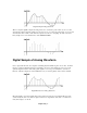
Original Simple Analog Waveform. When a computer digitally samples an analog audio wave, it starts at a point in time, say zero seconds, and reads the value of the audio at that point. Now, it moves on, to the next point in time, say one second, and reads this value of audio. Each time the computer does this, it is “sampling” the audio waveform. Every sample is stored on the hard drive of the SMARTCASTER: Digital Sample of Analog Waveform.
Types of SMARTCASTER Automation There are several ways to use a SMARTCASTER to automate a radio station. “Ultimation”, (Music on Hard Drive), Jock-In-the-Box, (Compact Disc), and Satellite are the three basic types of digital automation around today. Often, these can be combined. For example, it is not unusual for a station to combine a satellite news feed, a satellite talk show feed, and Music on Hard Drive for regular station programming.
Compact Disc Automation Many stations opt to automate with compact disc type automation. Instead of a satellite service determining what music goes over the air, the local station can develop its own personal type of music format. In this situation, the SMARTCASTER uses a CD controller computer to “talk” to the various CD decks. In addition, the SMARTCASTER can play back previously recorded commercials, weather bits, liners, jingles, etc.
SMARTCASTER is then wired to these relay closures in order to accept commands from a satellite service. It is very important that the SMARTCASTER be wired only to the dry relay contacts of the satellite receiver, and that these contacts never be wired to cart machines, or any other piece of equipment! If the SMARTCASTER is replacing an existing automation machine, take care not to wire the system with the cart machines or other equipment in parallel.
Satellite Automation Satellite control input and output, and satellite audio input and output to and from the SMARTCASTER are all accomplished through either a 37- pin D-connector located at the rear of the unit, or an Optional Breakout, (fan-out), card. A diagram of this 37- pin connector is included at the end of this section. If the system purchased contains an 8x4 Audio Switcher, please scan through this documentation, and then refer to the AMX 8x4 Switcher section later in this manual.
In the example below, a typical satellite receiver has been wired to the 37 pin connector in an optoisolated mode: Example for Satellite Control Wiring. Notice that the two Local Break closures are wired together. With the SMARTCASTER, all Local Break closures should be tied together. Programming within the SMARTCASTER allows for different Break lengths, times, etc. .
Satellite Audio Satellite Network audio is essentially unprocessed by the SMARTCASTER, but it is switched by relays in order to mute audio during a local commercial Break. For systems with just one satellite service, wire the satellite audio from the satellite receiver, through the four muting relays located on the 37 pin connector, and then back to the control board or mixer. (Note: The SMARTCASTER needs two inputs on the console: One for satellite audio, and a second for local audio from the hard drive.
you may audition one audio cut in cue while playing back another audio cut over the air. It is recommended that the ‘AUDITION’ output be wired into the console - not directly into some cue speakers. If wired into the board, the broadcaster is capable of dubbing spots from the SMARTCASTER to an alternative media source. End of Message Relay An End of Message, (EOM), relay closure is provided on the SMARTCASTER. This closure occurs at the end of the last spot played in a Local Break.
Relay 6 used to route Unattended Record source to SMARTCASTER inputs. 37- Pin Connector A complete diagram of the 37 pin connector is provided. It is suggested that the engineer make wiring notations on this page for future reference.
Jock-In-the-Box CD Automation System (NOTE: AS OF THIS WRITING –JULY, 1998 – WE ARE NO LONGER SELLING JIB SYSTEMS) The Jock-In-the-Box CD automation system requires some change of wiring from conventional satellite automation systems. With CD automation, comes the advent of dual processing. The main SMARTCASTER computer is the brain of the entire system and also stores all the digital audio recorded on the hard drive.
At this point in time, the Jock-In-the-Box is capable of automating the Pioneer PDM-502 and the PDTM4 consumer decks. (The 502 is the 6 CD player, and the TM series holds 18 discs.) The system is also compatible with the Pioneer CAC-V180M and CAV3200 professional decks. Interfacing the professional decks is a bit different than interfacing the consumer decks. Coverage of both types of installation will follow later in this section.
Summing Box for CD Audio Please try to keep these unbalanced lines away from AC power lines as much as possible. The audio output from the summing box is then routed to the unbalanced inputs of the dBX Buffer Amplifier. The balanced outputs are then connected to an input on the control board. Level adjustments for the CD audio are made at the Buffer Amp.
PCL 720 CARD (TTL I/O CARD) Diagram of digital I/O card for CD control. Next, take each individual control line from the Breakout cards and connect it to “Control In” of the appropriate CD deck. If one of the cables has come loose from the Breakout card, refer to the table below for connection information. All shields of the control cable should be connected to either pin 17 or 18 on the Breakout card, (GND). The tips should be connected as follows: Deck 1 - 16 : Pins 1 - 16 of the first card.
WIRING DIAGRAMS FOR COMMUNICATIONS CABLING Communciations Cable between CD CONTROLLER and SMARTCASTER. NOTE: While Com port connections are fairly standard, we may have to change things in the event that a modem is present in the SMARTCASTER. If the SMARTCASTER does contain a modem, please call for more information on connecting Comm Cables. Professional CD Players Please call SMARTS Broadcast Systems for information on the connection of these players.
Ultimation--Music on Hard Drive From the beginning, there has always been digital automation for those using a satellite format. However, others with specialty, “niche” formats or those who simply wanted their own station “sound”, were left in the cold. After satellite automation was conquered, SMARTS Broadcast Systems turned to the Jock-Inthe-Box CD automation system for this market.
Unattended Record Often, with Ultimation, a station simply wishes to air a news feed at the top of the hour. If the news is pre-recorded with the Unattended Record feature of the SMARTCASTER, no switching device is needed. Consult ‘UNATTENDED RECORD RELAY’ of the OPERATIONS section of this manual for further information. Generation 2000 The Generation 2000 SMARTCASTER line simplifies installation between several SMARTCASTERS.
is the last node in the line, connect one of the supplied 50 ohm terminators.
(Install LAN, cont..) It is very important that the LAN cable be run as a ‘line’ in a daisy-chain fashion instead of the ‘hub & spoke’ concept. The ‘hub & spoke’ wiring configuration will not work with this LAN Network. In addition, it is important that only RG58-U be used as cable, and that each end of the line is capped with 50 ohm terminators. Once the LAN is connected, all of the computers may be turned on.
the Network. In addition, any Verification Logs can be retrieved from the units. If an existing unit is being upgraded, please contact our Support Department in order to install the card and Lantastic software. SmartSwitch Node This computer node can handle any Network switching for multiple radio stations throughout the Network. Audio can be routed for Unattended Records or live air feeds to virtually any point at the installation site.
dBX Wiring for SMARTCASTER without Simultaneous Playback and Record. dBX Wiring for SMARTCASTER with Simultaneous Playback and Record.
Monaural Simultaneous Playback and Record For SMARTCASTERS equipped with the monaural version of Simultaneous Playback and Record, the dBX wiring can be accomplished with one dBX - even with two outputs. Use channel A of the dBX for audio from the console, through the dBX, and into the SMARTCASTER. Also use channel A for Audition audio coming from the SMARTCASTER, through the dBX, and into the Audition input on the console.
Setting Levels Setting the input levels involves synchronization of the VU meters at the source, (usually the production console or the audition bus of the Air console), with the SMARTCASTER input. To set the input gain, use complex audio modulation such as music, speech, or a spot, and set the gain so that the meters on the board read correctly. Next, engage all of the buttons of the front of the dBX units. Go into the Record Screen of the SMARTCASTER.
Installation of dBX 1024 Buffer Amplifier The dBX 1024 Buffer Amplifier is used as an impedance matching device between SMARTCASTERS with unbalanced input and outputs, and the console. Similar to a dBX 140, but without companding capabilities, it is often used with systems containing high quality audio cards. The dBX is also used to match levels and provide balanced inputs and outputs.
dBX 1024 FOR SIMULTANEOUS SYSTEMS dBX 1024 wiring for systems without Simultaneous Playback & Record. SMARTCASTERS without Simultaneous Playback & Record only have one output and one input. Therefore they need just one dBX unit. For stereo, it is suggested that the left channel be routed through channel 1 of the dBX. Right channel should be routed through channel 2. For monaural systems, simply use channel 1, and leave channel 2 free.
dBX 1024 FOR SIMULTANEOUS MONAURAL SYSTEM dBX 1024 wiring for Simultaneous Monaural System. Systems that have Simultaneous Playback & Record have one input, and two outputs: Audition and Air. Since the dBX 1024 has two independent channels, monaural systems with Simultaneous Playback & Record can also use one dBX unit. Channel 1 is used to route the Air output and channel 2 is used to route the Audition output.
dBX 1024 FOR SIMULTANEOUS STEREO SYSTEM dBX 1024 wiring for Simultaneous Stereo System. With a stereo, simultaneous SMARTCASTER, two dBX units are needed. One dBX matches both the Input and Air channels of the SMARTCASTER. The second unit simply matches the Audition output of the SMARTCASTER. (The XLR Input to RCA Output is left free.) Pin 1 Switch This switch internally disconnects the XLR Input pin 1, (both channels), from the 1024 Chassis Ground to eliminate any Ground loop hum problems that may arise.
Setting Levels Setting the input levels involves synchronization of the VU meters at the source, (usually the production console or the audition bus of the air console), with the SMARTCASTER input. To set the input gain, use complex audio modulation such as music, speech, or a spot, and set the gain so that the meters on the board read correctly. Go into the Record Screen of the SMARTCASTER.
Simple Network Switching There are several types of Network switching. The simplest version is a 2 in, 1 out Network Switcher based on a latching relay circuit. The next step up is a 5 in, 1 out Switcher, also based on relays. Finally, there is the 8 in, 4 out solid state Switcher. This section explains both the 2x1 and the 5x1 Switcher. For information on the 8x4 Switcher, refer to a later section in this manual. 2x1 Simple Network Switcher 2x1 Simple Network Switcher.
Finally, there is usually the need to disable the SMARTCASTER from seeing relay closures from the primary audio source while on the secondary audio source, and vica versa. In our example, we would want to keep the SMARTCASTER from seeing, (and playing), a jingle while the news is on the air. In order to do this, the 12 volt line wired in series with the satellite receiver relay closures, can be switched away from the primary, to the secondary, via the switching contacts on pin four of the horizontal strips.
5x1 Network Switcher The 5x1 Network Switcher, while based on relay technology, is wired a bit differently than the 2x1 Switcher. 5x1 Switcher shown with control wiring from SMARTCASTER. The top horizontal strip is the normally closed position for the five different inputs. The second strip is the normally open position for the five different inputs. In almost all cases, audio inputs should be wired to the normally open positions, (the second strip). The first strip should only be used in special cases.
5x1 wiring to prevent closures being sensed by SMARTCASTER from Networks not on the air. In the example above, there are three Networks wired to the 5x1 Switcher, and all have relay closures. Pins 30-37 of the 37 pin connector, (Digital Input Low’s), are connected to the GND connection on the 5x1 Switcher. Next, each satellite receiver has one side of all of its relays bussed together, and connected to its control line on the 5x1 Switcher.
Ribbon Cable Connections Three 20-pin flat ribbon cables, one 64-pin flat ribbon cable, and a gold 8x4 Switcher Harness Card, (see below), should be included with the 8x4 Switcher. This card is used to make connections between the SMARTCASTER and the 8x4 Switcher. In addition, all satellite relay closures are wired into this card. AMX 8x4 Switcher Harness On the SMARTCASTER are four 20- pin female connectors, labeled CON 1, CON 2, CON 3, and CON 4. Connect CN 1 to CON 1 with a 20-pin flat ribbon cable.
Output Wiring Of the four outputs on the 8x4 Switcher, only two are needed. Output 1 is routed to an input on the console, and output 2 is routed to the record inputs of the SMARTCASTER. 8x4 Switcher output wiring. Unbalanced feeds are connected with the center conductor wired to the ‘+’ terminal, and the shield connected to Ground. The ‘-‘ terminal is not used with unbalanced connections. For balanced connections, the Ground terminal is provided if needed.
Input wiring AMX 8x4 Switcher - rear view. Audio inputs can either be balanced or unbalanced. Balanced audio should be connected to the ‘+’ and ‘-‘ terminals. The shield can be connected to the Ground terminal. With unbalanced connections, the ‘hot’ line or center conductor should be connected to the ‘+’ terminal. The shield should then be connected to Ground. The ‘-‘ terminal is not used in the case of unbalanced connections. Input connection for 8x4 Switcher.
Audition Channel of Control Board through 8x4 Switcher If the AMX Switcher is to be used for Unattended Recording AND normal studio production, the audition channel of the console must be wired into an input on the 8x4 Switcher. When this feature is enabled, the SMARTCASTER automatically routes the audition channel to the record inputs of the SMARTCASTER when the user enters the Record/Audition Screen.
Digital Inputs for Relay Closures All relay connections to the 8x4 Switcher are made via the two terminal strips located at the corner of the 8x4 Harness Card. All connections should be made with dry contact closures.
Example relay closure wiring to AMX Harness Board. Again, do not worry about disabling relay closures in the event that one satellite receiver might fire a closure while another satellite feed was on the air. With the AMX 8x4 Switcher, the SMARTCASTER software keeps track of which digital inputs are valid during the time that each Network is on the air. Make sure the SMARTCASTER is setup properly to acknowledge relay closures through the AMX Harness and not the standard relay card.
Theoretically, levels should now be the same for all inputs. However, if a channel through output 1 of the Switcher needs to be checked, go to the main automation Screen of SMARTCASTER.
Pin 1 3 5 7 9 11 13 15 17 19 Input Input 1 Input 3 Input 5 Input 7 Input 1 Input 3 Input 5 Input 7 Ground 5 Volts DC Output Output Output Output Output Output Output Output Output Pin 1 1 1 1 2 2 2 2 2 4 6 8 10 12 14 16 18 20 Input Output Input 2 Output Input 4 Output Input 6 Output Input 8 Output Input 2 Output Input 4 Output Input 6 Output Input 8 Output Ground 12 Volts DC 2 4 6 8 10 12 14 16 18 20 Input Output Input 2 Output Input 4 Output Input 6 Output Input 8 Output Input 2 Output Input 4 Outpu
Isobar Line Filter The Isobar Line Filter is used to protect the system from lightning strikes and line surges. It should be plugged into an AC outlet, and the UPS Power Supply should then be plugged into an outlet on the Isobar Line Filter. DO NOT PLUG ANY PART OF THE SMARTCASTER DIRECTLY INTO AN AC PLUG. UPS Power Supply The UPS (Uninterruptable Power Supply) provides a backup power supply in case a power outage occurs.
We cannot emphasize enough how important this operation is to the SMARTCASTER. Please do not neglect this duty. Defrag Instructions To run Defrag, go to the main menu of the SMARTCASTER. Reset the computer. Next, if ‘Optimization’ is on the main menu, select it. Otherwise, press u to get to the C:> prompt, and type: DEFRAG /F and press e Once in the Defrag program, the system asks which drive to Optimize. Highlight the correct drive and press e. Defrag now Optimizes the drive.
Engineering - 47
Audio Card Descriptions Over the years, SMARTS Broadcast Systems has used many different types of audio cards in many different configurations. Some have used RCA unbalanced connections, others have used balanced 9- pin D-sub connectors, while others have used a 37- pin D-sub connector. This portion of the manual should serve as a description of each card, and how to connect audio lines to and from the SMARTCASTER. The VP-635 and SX audio card series are manufactured by Antex Electronics in California.
SX-7 This card is capable of Playback only. It has no Recording capability. Generally, this card is combined with the SX-12, SX-20, or SX-22 in order to provide Stereo or Overlap capabilities. The card can use either the ADPCM or Dolby-AC2 digital audio algorithms, and it can perform Shrink-and-Expand Operations. Connections can be made in two places. There are two RCA connections for unbalanced -10dB audio, or there is a 9 pin D-sub connector for +16dB balanced audio.
100D & ACE Pro Due to their ability to be Networked using LAN technology, ACE cards are found on all Generation 2000 productions. ACE cards use the Apt-X audio compression algorithm. They are not capable of Shrinkand-Expand. The 100D is the Playback only version. The Pro card can Record and Playback. In order to achieve Overlap, two ACE 100D cards must be connected together in parallel. The ACE cards can achieve up to 16 KHz stereo. All ACE cards use a 37- pin D-sub connector for audio connections.
AudioPort Installation Instructions Some SMARTCASTER systems, (for example, the SatPak), use the AudioPort instead of the internal audio card for storing audio on the hard drive. In these cases, wiring for local audio is a bit different. To begin the installation, the external AudioPort must be connected to the SMARTCASTER. A cord can be found attached to the back of the AudioPort which branches out to a T-connector. Simply connect the keyboard to the female side of the T-connector.
switches, open the rack-mount, and locate the dip switches on the PC board. Please take care not to accidentally disconnect any wiring. The SmartTouch is already configured with the security code “8888”. To change the security code, refer to the table on the following page. There are six switches labeled zero through five. A zero is ON and a one is OFF.
SmartTouch cont...
Back Panel of SmartTouch. If the station is using satellite automation, connect the satellite feed to the Net In connection. If there is more than one Network, connect the output of the switching equipment to this connection. Next, take a balanced monaural air monitor, and connect it to the Air Cue terminals. Now connect the Sys. Out to an input on the control board. Since the SmartTouch mutes the Network audio, there is no need to wire anything through the muting relays on the 37- pin connector.
Wiring SmartTouch into an existing SMARTCASTER If adding the SmartTouch to an already existing SMARTCASTER, some additional steps are needed. First, a card, (PCL-720 Digital I/O Card), needs to be installed into an empty card slot in the computer. This card sends and receives the one’s and zero’s used to communicate with SmartTouch. To insert the card, remove the cover from the SMARTCASTER, and locate an empty card slot. Remove the filler panel for the slot, and insert the card.
Front Panel There are several switches and LED’s on the front of the SmartTouch that merit explanation. The leftmost LED is the power light. When the SmartTouch is plugged in, this light should be on. There is no power switch. The next button is the Reset button. If for any reason, the system needs to be reset, simply push this button. The SmartTouch goes off hook for a few seconds, and then is ready to accept calls. The next switch is the Security Defeat switch. When switched on, the Sec.
Watchdog: The Watchdog is an additional device that can be purchased with the SMARTCASTER. It is an electronic device which monitors the SMARTCASTER for lockups. The SMARTCASTER sends an electronic pulse to the Watchdog every so often. If at any time, this pulse train stops, the Watchdog assumes the SMARTCASTER has locked up. It then tries to rectify the situation by resetting the SMARTCASTER.
Modification in the Field If a Watchdog is being added to a SMARTCASTER in the field, some additional steps are needed. Included in the upgrade is a computer card, (PCL 720 - Digital I/O Card), and a wiring Harness. First, the card needs to be installed into an empty card slot in the computer. This card sends the pulse train to the Watchdog.
Front Panel The front panel consists of two switches, one reset button, and several LED’s. If using the Watchdog to monitor two SMARTCASTERS, the switch on the far left should be armed. However, if the Watchdog is monitoring only one SMARTCASTER, this switch should be in the Disarm position. Front Panel of Watchdog. To the right of the Arm switch is a series of diagnostic LED’s. The “Monitor” LED flashes every time the SMARTCASTER sends a pulse to the Watchdog.
Test of Installation There is a simple way to test the installation of the Watchdog. Located on the keyboard of the SMARTCASTER is a “PAUSE” key. If this key is pressed, it locks the microprocessor of the SMARTCASTER until another key is pressed. To run the test, simply press the Pause key in a portion of the SMARTCASTER program that has armed the Watchdog. If the installation has been performed correctly, the Watchdog should reset the computer after 20-30 seconds.
Silence Sense Alarm The SMARTCASTER can be equipped with a Silence Sense Alarm to start the SMARTCASTER back up when 30 seconds of silence is detected. In some systems, the Silence Sense can be wired to trip the SMARTCASTER into starting again. In other systems, the Silence Sense must be wired to actually reset the computer. In all cases, it is important to remember that the Silence Sense must always have audio being fed to it. If audio is not present, the Silence Sense will activate.
CD Automation Systems If the SMARTCASTER is used as a CD automation system, wire the reset terminals from the Silence Sense to the Local Break input on the 37 pin connector: Music on Hard Drive or Satellite Automation In these automation systems, it is best to reset the SMARTCASTER computer. If wiring a Silence Sense to a brand new SMARTCASTER, there should be a port labeled, ‘RESET’ on the back of the computer. If not, it is not difficult to make one. Open the SMARTCASTER case.
Opto-Isolation Presently, most SMARTCASTERS are shipped in an Opto-Isolation mode. This modification helps protect the unit against lightning damage and damage caused by electrical surges. It also allows the unit to operate in high RF fields that might cause random Break firings if the control circuits are not isolated. (Units using the 8x4 Switcher do not operate with Opto-Isolation.
Communications Cable There are several instances during a SMARTCASTER installation in which a communications, (comm), cable is needed. Connections with a Remote Record unit or CD Server unit to the SMARTCASTER all require a comm cable. The comm cable is linked between the serial, RS-232, ports of each computer. In the case that a comm cable needs to be built or repaired, two female D-Sub connectors are need. These should be in the 9 pin or 25-pin configuration.
On the comm cable, some of the signals need to be shorted together within the D-sub connector. Others need to be connected across the cable to pins at the other end. Below are wiring diagrams for each cable configuration: 9-pin to 9-pin, 25-pin to 25-pin, and 9-pin to 25-pin. Comm cable wiring configurations for 9-and 25-pin connectors. Note: Due to the large voltage swings of RS-232, it is not advisable to run a comm cable through a patch panel or multi-pair cable also containing audio.
2 C 2x1 Simple Network Switcher, 28 3 37 Pin Connector, 11 5 50 ohm terminators, 17, 18 5x1 Network Switcher, 30 8 8x4, 7, 13, 16, 28, 31, 32, 33, 34, 35, 36, 37, 38, 39, 40, 41, 57 CAC-V180M, 12 CAV3200, 12 CD Audio Wiring, 12 CD Automation Systems (and Silence Sense), 56 CD Control Lines, 13 CD server, 12, 13, 40 Comm Cable, 14, 41 Comm Cable Between CD Server and SMARTCASTER, 14 Comm CableError! Bookmark not defined.