TLP 1 OPERATING MANUAL w w w. a n t h e m AV.
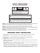
SAFETY PRECAUTIONS READ THIS SECTION CAREFULLY BEFORE PROCEEDING! WARNING RISK OF ELECTRIC SHOCK DO NOT OPEN WARNING: TO REDUCE THE RISK OF ELECTRIC SHOCK, DO NOT REMOVE COVER (OR BACK). NO USERSERVICEABLE PARTS INSIDE. REFER SERVICING TO QUALIFIED SERVICE PERSONNEL. The lightning flash with arrowpoint within an equilateral triangle warns of the presence of uninsulated “dangerous voltage” within the product’s enclosure that may be of sufficient magnitude to constitute a risk of electric shock to persons.
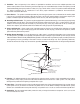
8. Ventilation – Slots and openings in the cabinet are provided for ventilation and to ensure reliable operation of the product and to protect it from overheating, and these openings must not be blocked or covered. The openings should never be blocked by placing the product on a bed, sofa, rug, or other similar surface. This product should not be placed in a built-in installation such as a bookcase or rack unless proper ventilation is provided or the manufacturer’s instructions have been adhered to. 9.
16. Object and Liquid Entry – Never push objects of any kind through openings as they may touch dangerous voltage points or short-out parts that could result in a fire or electric shock. Do not expose this product to dripping or splashing and ensure that no objects filled with liquids, such as vases, are placed on the product. 17. Servicing – Do not attempt to service this product yourself, as opening or removing covers may expose you to dangerous voltage or other hazards.
TABLE of CONTENTS SECTION PAGE 1. INTRODUCTION 1 1 Receiving and Unpacking the TLP 1 . . . . . . . . . . . . . . . . . . . . . . . . . . . . . . . . . . . . . . . . . . . . . . . . . . . . . . 1 1.1 Packing List 1 1.2 Important Safety Information . . . . . . . . . . . . . . . . . . . . . . . . . . . . . . . . . . . . . . . . . . . . . . . . . . . . . . . . . . . . 1 1.2.1 Before Operating Your TLP 1 1 1.2.2 Supply Power Requirements 2 1.2.3 In-Use Notices 2 1.3 Packing Materials . . . . . . . . . . . .
4. REMOTE CONTROL OPERATION 16 4.1 Powering the TLP 1 ON and OFF . . . . . . . . . . . . . . . . . . . . . . . . . . . . . . . . . . . . . . . . . . . . . . . . . . . . . . . . 16 4.2 Direct FM•AM Station Entry . . . . . . . . . . . . . . . . . . . . . . . . . . . . . . . . . . . . . . . . . . . . . . . . . . . . . . . . . . . 16 4.3 Controlling Other Components . . . . . . . . . . . . . . . . . . . . . . . . . . . . . . . . . . . . . . . . . . . . . . . . . . . . . . . . . . 17 4.3.
1. INTRODUCTION Thank you for purchasing the Anthem TLP 1 Preamplifier • Tuner. Anthem Electronics has been manufacturing high-quality, high-end audio equipment for over a decade. In that time, Anthem has built an enviable reputation for products that can recreate the passion a music lover experiences when attending a live musical performance, or the thrilling sound a movie buff experiences in the very best movie theaters.
1. INTRODUCTION continued … 1.2.2 SUPPLY POWER REQUIREMENTS The TLP 1 operates from a single phase AC power source that supplies between 105V and 130V at a frequency of 60 Hz. It cannot be changed from 120V to 240V operation. 1.2.3 IN-USE NOTICES • Use only the power supply cord with double insulation as supplied. • Disconnect the amplifier’s power cord before connecting or disconnecting any components. • Do not remove the top cover. • Do not alter or modify the amplifier in any way.
2. CONNECTIONS AND LAYOUT With your TLP 1 in front of you, browse through the illustrations in this section to see several quick system hookup options. It’s as simple as following the lines in the connection diagrams to and from each component. 2.1 QUICK START GUIDE – Before you start, make sure all components are unplugged. To connect a CD player, DVD player, TV, VCR, amplifier, and powered subwoofer to the TLP 1: • CD Player to TLP 1 – see diagram in section 2.3.
2. CONNECTIONS AND LAYOUT continued … 2.
2. CONNECTIONS AND LAYOUT continued … 2.2.1 FRONT PANEL DISPLAY Main Display Example: 2 1 1 – Source selection. 2 – Volume setting. When muted, “Muted” flashes instead of the current volume setting. FM•AM Display Example: 1 2 3 1 – Source+Bank. The tuner has three FM banks (FM1, FM2, and FM3) and one AM bank. The number after the selected bank is the preset station. 2 – FM mode. Displays “St” when in stereo, “HB” when Hi-Blend is selected, or “Mn” when in mono or mono is selected.
2. CONNECTIONS AND LAYOUT continued … 2.3.
2. CONNECTIONS AND LAYOUT continued … 2.3.2 DVD Player and Satellite Receiver to TLP 1 SATELLITE Component Video Out Satellite Receiver Y Digital Out Audio Out R L RCA Composite Video Out S-Video Out Toslink Pb Pr Note: Connect video output to TV. DVD Amplifier Note: Connect video output to TV.
2. CONNECTIONS AND LAYOUT continued … 2.3.3 VCR and TV to TLP 1 Rear Panel of TV Audio Out Y CATV In Composite Video In L Vari Pb Fixed S-Video In R Pr Note: Connect video output from source components to TV. Note: If using a satellite receiver and a TV monitor that does not have audio inputs and outputs, connect satellite receiver’s audio outputs directly to SAT•AUX. VCR EJECT Note: Connect video output to TV.
2. CONNECTIONS AND LAYOUT continued … TLP 1 to Amplifier and Powered Subwoofer – Small Speakers Powered Subwoofer Input WE PO 2.3.4 RCA R Level Note: If subwoofer does not have a built-in crossover, use Low Pass output instead of Full Range. P V A RIG H T IN P U T 2 SERIAL NO.
2. CONNECTIONS AND LAYOUT continued … 2.3.5 TLP 1 to Amplifier and Powered Subwoofer – Full Range Speakers Powered Subwoofer PO WE R Input RCA Level Note: If subwoofer does not have a built-in crossover, use Low Pass output instead of Full Range. M C A VA 10 20 WARNING RISK OF HAZARDOUS ENERGY! MAKE PROPER SPEAKER CONNECTIONS. SEE OPERATING MANUAL BEFORE USING.
2. CONNECTIONS AND LAYOUT continued … 2.
2. CONNECTIONS AND LAYOUT continued … 2.5 CONNECTING POWER TO THE TLP 1 Connect the power cord to the back of the TLP 1 and then to an AC outlet. If excessive hum or buzz is heard through the speakers during operation, remove the cord from the back of the TLP 1 and re-insert it after turning the connector upside down. 2.6 AUDIO INPUTS Audio connections are made through interconnect cables – typically white or black for the Left channel and red for the Right channel.
2. CONNECTIONS AND LAYOUT continued … Headphone: When a headphone plug is inserted into the headphone jack on the front panel, all audio outputs on the rear panel are muted. 2.8 FM•AM ANTENNAS To connect the FM antenna, first connect the two antenna wires to the screw terminals of the 75-ohm to 300-ohm adapter. Then connect the adapter to the FM ANTENNA connector on the TLP 1. If your local cable company provides FM service, connect the cable directly to the TLP 1 instead of using the antenna.
3. FRONT PANEL OPERATION 3.1 POWER ON/OFF When turned on, the TLP 1 will have all of the same settings it had when it was last turned off, except for Volume, which comes on at -30 dB. 3.2 MASTER CONTROL KNOB Besides being a Volume Control, the MASTER CONTROL KNOB also operates other functions, including adjustment of Bass / Treble / Balance, FM•AM tuning, Input Level, and Display Brightness selection. Mute: When MUTE is pressed, the audio output is silenced.
3. FRONT PANEL OPERATION continued … Presets: 18 FM and 6 AM stations can be stored in the TLP 1. The presets are divided into four banks of six. By repeatedly pressing FM • AM, the display will show that you are cycling through ‘FM1’, ‘FM2’, ‘FM3’, ‘AM’. Once you have selected the desired bank, you can store the currently tuned radio station by pressing and holding one of the six preset keys (1 through 6) for about a second. You can even do this while scanning for stations.
4. REMOTE CONTROL OPERATION The TLP 1 Universal Remote Control has all of the same functions as the front panel buttons and is operated in a similar way, but there are some differences. Please take the time to read this section to fully understand all the functions of the TLP 1 Remote Control. IR Transmitter Power ON Transmission Indicatior Setup Mode Control Mode The keys labeled in this illustration show those that have a different method of operation from their front panel counterparts.
4. REMOTE CONTROL OPERATION continued … 4.3 CONTROLLING OTHER COMPONENTS The TLP 1 Remote Control can be set up to control your TV, DVD player or VCR, and satellite receiver or cable converter. It contains a set of codes for models from many different manufacturers, which can be entered to virtually duplicate another remote control. 4.3.1 ENTERING PRESET MEMORY CODES In Appendix A, at the back of this manual, you will find codes for programming the TLP 1 remote. To enter a preset memory code: 1.
4. REMOTE CONTROL OPERATION continued … In the following example, TLP volume is locked onto every Component selection except TV: To Engage Volume Lock for TLP: 1. Press and hold SETUP until the LED flashes twice. 2. Press 9, 9, 3. 3. Press TLP. At this point, the Volume and Mute keys now control the TLP 1, no matter which of the four Component selections the Remote Control is in. However, since this may not be desirable, any individual Component selection can be unlocked.
APPENDIX A – PRESET MEMORY CODES VCR and Laser Disc player codes can be programmed into the DVD key, and Cable Converter codes can be programmed into the SAT key. To enter a code: 1. 2. 3. Press the Component key (e.g. TV). Press and hold SETUP until the LED flashes twice. Enter the four-digit code. The LED should blink twice.
APPENDIX A – PRESET MEMORY CODES continued … MTC Magnasonic Magnavox Magnin Marantz Marta Matsushita Memorex Minolta Mitsubishi Motorola Multitech NAP NEC Nikko Noblex Olympus Optimus Orion Panasonic Penney Pentax Philco Philips Pilot Pioneer Profitronic Proscan Protec Pulsar Quarter Quartz Quasar RCA Radio Shack Radix Randex Realistic Runco STS Samsung Sanky Sansui Sanyo Scott Sears Semp Sharp Shintom Shogun Signature Singer Sony Sylvania Symphonic TMK Tatung Teac Technics Teknika Thomas Toshiba Totevisio
SPECIFICATIONS PREAMPLIFIER Input Impedance . . . . . . . . . . . . . . . . . . . . . . . . . . . . . . . . . . . . . . . . . . . . . . . . . . . . . . . . . . . . . . . . . . . . . . 25 kΩ Main Output Impedance. . . . . . . . . . . . . . . . . . . . . . . . . . . . . . . . . . . . . . . . . . . . . . . . . . . . . . . . . . . . . . . . 300 Ω Record Output Impedance . . . . . . . . . . . . . . . . . . . . . . . . . . . . . . . . . . . . . . . . . . . . . . . . . . . . . . . . . . . . . . .
SPECIFICATIONS continued … FM TUNER Sensitivity 50 dB S/N . . . . . . . . . . . . . . . . . . . . . . . . . . . . . . . . . . . . . . . . . . . . . . . . . . . . 13 dBµ typ., 25 dBµ max. IHF . . . . . . . . . . . . . . . . . . . . . . . . . . . . . . . . . . . . . . . . . . . . . . . . . . . . . . . . . . 10 dBµ typ., 20 dBµ max. S/N Ratio Mono . . . . . . . . . . . . . . . . . . . . . . . . . . . . . . . . . . . . . . . . . . . . . . . . . . . . . . . . . . . 75 dB typ., 65 dB min. Stereo . . . . . . . . .
LIMITED WARRANTY CANADA & USA The warranty period on Anthem products is five (5) years for power amplifiers and integrated amplifiers, three (3) years for audio preamplifiers and audio processing, two (2) years for video equipment and video processing, one (1) year for remote controls, and six (6) months for projector lamps from date of purchase from Anthem or an Authorized Anthem Dealer.
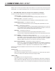
THE BIG PICTURE FRONT PANEL
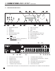
THE BIG PICTURE REAR PANEL
DESIGNED AND MANUFACTURED IN NORTH AMERICA t e l . ( + 1 ) 905-362-0958 M-F 9:00 am - 5:30 pm (ET) www.anthemAV.