
Assembly Instructions Owner manual
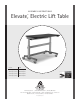
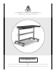

Elevate,
TM
Electric Lift Table Assembly Instructions
3
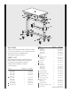
PARTS LIST (CONTINUED)
20 20mm Socket Head Cap Screw 16 325-5272-00
21 3/4" Phillips Screw 4 325-5370-00
22 1-1/4" Button Head Screw 16 325-5178-00
Product Quantity Part Number
23 Hex Driver (not shown) 1 375-5000-00
24 1/4" Hex Key (not shown) 1 375-5024-00
25 Rubber Mallet (not shown) 1 375-5022-00
26 5mm Hex Key (not shown) 1 375-5014-00
27 5/32" Hex Driver Bit (not shown) 1 375-5003-00
28 10’ Power Cord (not shown) 1 400-5181-00
Product Quantity Part Number
For 36” and 48” wide Elevates
29 1-meter Control Box Cable (not shown) 2 400-5182-00
For 60” and 72” wide Elevates
30 1-meter Control Box Cable (not shown) 1 400-5182-00
31 2-meter Control Box Cable (not shown) 1 400-5180-00
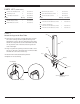
STEP 1
Attach the Legs to the Base Tubes
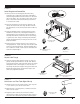
¡ Hold one leg so the Slot is facing away from you and
the cord is coming out the top. Route the leg cord
through the notch on the top. Using the mallet, firmly
attach the cord grommet to the notch. Make sure that
one leg has the cord on the left and one leg has the
cord on the right.
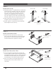
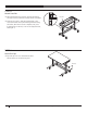
¡ Align a leg with the opening on the base tube so that
the slot on the legs is facing the hole on the base tube
and that the cord comes out the top.
¡ Attach with four Socket Head Cap Screws.
¡ Repeat for the second leg.
20mm Socket Head Cap Screw
325-5272-00
Leg
Basetube
Slot
Rear
Front
Hole
Cord Grommet
Notch