80 Kehoe Blvd. Carol Stream, Illinois 60188 USA 1-877-392-7854 (Tech Service).
CCC-20 TRAINING CCC-20 TECHNICAL MANUAL LAST UPDATE 5-1-05 1060005 5/05
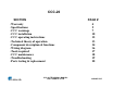
CCC-20 SECTION •Warranty •Specifications •CCC warnings •CCC installation •CCC operating instructions •Technical theory of operation •Component description & functions •Wiring diagram •Tools required •CCC maintenance •Troubleshooting •Parts testing & replacement CCC-20 TECHNICAL MANUAL LAST UPDATE 5-1-05 PAGE # 4 5 7 10 12 13 14 16 17 18 19 20 1060005 5/05
WARRANTY Equipment manufactured by Roundup Food Equipment Division of A. J. Antunes & Co. has been constructed of the finest materials available and manufactured to high quality standards. These units are warranted to be free from mechanical and electrical detects for a period of one year from date of purchase under normal use and service, and when installed in accordance with manufacturers recommendations.
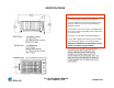
SPECIFICATIONS ▲ ELECTRICAL SHOCK HAZARD ▲ • Electrical ground is required on this appliance. • Do Not modify the power supply cord plug. If it does not fit the outlet, have a proper outlet installed by a qualified electrician. • Do Not have a fuse in the neutral or grounding circuit. A fuse in the neutral or grounding circuit could result in an electrical shock. • Do Not use an extension cord with this appliance.
SPECIFICATIONS CCC-20 TECHNICAL MANUAL LAST UPDATE 5-1-05 1060005 5/05
▲ WARNINGS ▲ CCC-20 TECHNICAL MANUAL LAST UPDATE 5-1-05 1060005 5/05
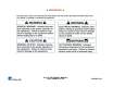
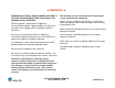
▲ WARNINGS ▲ In addition to the warnings and cautions in this manual, use the following guidelines for safe operation of the unit. Do not immerse cord or plug in water. Read all instructions before using equipment. Do not allow cord to hang over edge of table or counter. For your safety, the equipment is furnished with a properly grounded cord connector. The following warnings and cautions appear throughout this manual and should be carefully observed. Keep cord away from heated surfaces.
▲ WARNINGS ▲ WARNING ELECTRICAL SHOCK HAZARD. FAILURE TO FOLLOW THESE INSTRUCTIONS COULD RESULT IN SERIOUS INJURY OR DEATH. Electrical ground is required on this appliance. Do not modify the power supply cord plug. If it does not fit the outlet, have a proper outlet installed by a qualified electrician. Do not use an extension cord with this appliance. Check with a qualified electrician if you are in doubt as to whether the appliance is properly grounded.
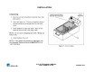
INSTALLATION CCC-20 TECHNICAL MANUAL LAST UPDATE 5-1-05 1060005 5/05
INSTALLATION CCC-20 TECHNICAL MANUAL LAST UPDATE 5-1-05 1060005 5/05
OPERATION CCC-20 TECHNICAL MANUAL LAST UPDATE 5-1-05 1060005 5/05
CCC-20 TECHNICAL THEORY OF OPERATION When the unit is plugged into the outlet, line voltage flows to the normally open (N.O.) safety interlock switch*. Once its contacts close, line voltage then flows to the input side of the power switch. When the power switch is turned on, line voltage then flows to a normally closed (N.C) capillary bulb style thermostat**.
CCC-20 Component Description & Function Head Assembly: It is the main assembly which consists of the following electrical components: heating element, power cord, power switch, thermostat, safety interlock switch, terminal block, & indicator light. NOTE: The heating element will not operate if the head assembly is not properly seated onto the pan, or is being operated without the pan. Power Switch: Double Pole Single Throw, turns the voltage On or Off to the unit’s internal components.
Component Description & Function Thermostat: A normally closed (N.C.) capillary bulb style thermostat. The bulb monitors the water temperature. It will cycle the heating element on & off as needed to maintain water temperature at approximately 162° F (72° C). Green Light: Used on all CCC-20’s except CCC-20 with Mfg # 9600214. It is a line voltage indicator light that is located on the head assembly. It is wired in parallel to the thermostat.
WIRING DIAGRAM CCC-20 TECHNICAL MANUAL LAST UPDATE 5-1-05 1060005 5/05
TOOLS REQUIRED FOR REPAIR & TROUBLESHOOTING (VOM) Volt Ohm Meter (digital or analog) Clamp type amp meter (digital or analog) Flat blade screwdriver ¼ " Adjustable wrench 6“ Nut driver set Channel locks Wire cutter, crimper, stripper Needle nose pliers.
MAINTENANCE CCC-20 TECHNICAL MANUAL LAST UPDATE 5-1-05 1060005 5/05
TROUBLESHOOTING CCC-20 TECHNICAL MANUAL LAST UPDATE 5-1-05 1060005 5/05
CCC-20 Parts Testing & Replacement Procedures CCC-20 TECHNICAL MANUAL LAST UPDATE 5-1-05 1060005 5/05
TESTING HEAD ASSEMBLY See Head Assembly under “Component Description & Function” before proceeding. If any of the head assembly’s electrical components are malfunctioning, each component must be tested individually TESTING POWER SWITCH See Power Switch & Splash Guard under “Component Description & Function” before proceeding. Disconnect wires to isolate switch. Turn switch to the “On” position. Verify continuity across terminals 1 & 2, then 4 & 5. Next, turn switch to the “Off” position.
TESTING SPLASH GUARD See Splash Guard under “Component Description & Function” before proceeding. The splash guard is typically trouble free. If it is damaged or missing, it must be replaced. Replacement Procedures Remove service panel. Disconnect power switch wires (Mark for reinstallation). Squeeze locking tabs inward & push switch away from unit. Reinstall switch & new splash guard. NOTE: If splash guard is damaged or missing, it must be replaced.
TESTING SAFETY INTERLOCK SWITCH See Safety Interlock Switch under “Component Description & Function” before proceeding. Disconnect wires to isolate switch. Verify continuity across the switch with the plunger manually depressed. Next, release plunger. Reading should now be infinity. Replace if fails test. Replacement Procedures Remove service panel. Disconnect switch wires. Remove the two mounting screws. Install new switch along with the new o’ring & secure with screws.
TESTING SAFETY INTERLOCK SWITCH O’RING See Safety Interlock Switch O’ring under “Component Description & Function” before proceeding. The safety interlock switch o-ring is typically trouble free. If it is damaged, it must be replaced. Replacement Procedures Follow the “safety interlock switch replacement procedures”. NOTE: The o’ring must always be used. Failure to do so may result in water/moisture damage to electrical components. Test unit for proper operation.
TESTING TERMINAL BLOCK See Terminal Block under “Component Description & Function” before proceeding. Verify continuity across each of the three poles. Replace if it fails test or if damaged. Replacement Procedures Remove service panel. Remove the two mounting screws & nuts. Disconnect terminal block wires (Mark for reinstallation). Reinstall wires onto new terminal block & secure with screws & nuts. Test unit for proper operation.
TESTING HEATING ELEMENT See Heating Element under “Component Description & Function” before proceeding. Disconnect wires to isolate heating element. Verify 8 ohms +/- 1 for 120 volt heating element. Verify 28 ohms +/- 1 for 230 volt heating element. Check from each terminal to ground using at least a 20M scale. Reading should be infinity. Replace if fails either test. Replacement Procedures Remove service panel. Disconnect element wires. Remove clamps & capillary bulb tubing from old element.
TESTING THERMOSTAT See Thermostat under “Component Description & Function” before proceeding. To test thermostat for continuity: Disconnect thermostat wires to isolate. Verify continuity across terminals. Replace if fails test. To determine if an “over heating” condition is caused by a faulty thermostat: Fill the pan with hot water about 1” (2.5 cm) above the thermostat bulb. Turn unit on & monitor the water temperature for at least 30 minutes.
TESTING “GREEN” OR “AMBER” INDICATOR LIGHTS See Green & Amber lights under “Component Description & Function” before proceeding. Does the light turn on? If no, is there line voltage present across the indicator light? If yes, replace light. Replacement Procedures Remove service panel. Disconnect the indicator light wires. Push the light up & away from the unit. Install new light into place until flush. Reinstall wiring onto light. Test unit for proper operation.
TESTING PAN See Pan under “Component Description & Function” before proceeding. The pan is typically trouble free. If it is damaged, it must be replaced. Replacement Procedure Remove the bottom panel. Remove the pan’s 4 hex nuts. Remove pan. Install new pan & secure with hex nuts. Test unit for proper operation.
TESTING BASKETS See Baskets under “Component Description & Function” before proceeding. The baskets are typically trouble free. If they are damaged, they must be replaced.