Quick Guide POS50 Series April. 2006 (V1.
CONTENTS Chapter 1 Unpacking -------------------------------------------------------------------------------- 3 Chapter 2 Specification -------------------------------------------------------------------------------- 4 2.1 Specification 2.2 I/O Ports Chapter 3 Installation --------------------------------------------------------------------------------- 6 3.1 OS Installation 3.2 Touch Driver Installation 3.3 MSR / I Button PS2 Interface Installation 3.
Chapter 1 Unpacking Unpacking the POS Terminal, please check the following items are presented and in good conditions: a. Main Unit b. CD: User’s Manual & Driver Bank The driver disk includes user’s manual and all of driver software of peripheral, such as touch screen, VGA, LAN….etc. c. Power Cord: Optional USA, Europe, UK or Australia type.
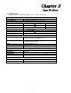
Chapter 2 Specification 2.1 Specification The POS system configuration including 8.4”, 12.1” and 15” as followings, CPU System Memory TFT LCD Size Brightness Resolution Touch Screen HDD Compact Flash Serial Main Board AMD Geode LX-800 1 x DDR400 SO-DIMM Socket, up to 1GB Display 8.4” 12.1” 15” 180nits 300nits 250nits 800x600 1024x768 5 Wire Resistive Type Storage Device No Support 2.
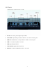
2.2 I/O ports Following ports show all of ports of system. a. DC IN: connector for power adapter input 12VDC. b. Cash Drawer: provide IO port address 280H for cash drawer control by RJ11. c. COM 1/2: standard D sub serial port with 5V / 12VDC selected on pin9. d. LAN: 10 / 100 base-T by RJ45 connector. e. USB: play and plug USB 2.0. f. Power Switch: toggle switch for power on. g. MSR PS2: for attached MSR PS2 interface connection.
Chapter 3 Installation 3.1 OS Installation 3.1.1 Embedded WEPOS / WinCE CD ROM Driver with USB interface If you bought the system including WEPOS / WinCE operation system, please follow up below procedure. a. Connect CDROM to the USB port of system. b. Turn on the system and enter completely into WEPOS. c. Up load your application software into WEPOS platform. d. Complete installation and execute the AP.
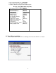
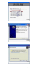
d. Select “First Boot Device” to “USB-CDROM”. e. Press “F10” to save setup change and quit. f. Install the Win XP, follow up the OS installation guide.
3.3 MSR / I-Button PS2 interface Installation a. The MSR Kit included Bracket and Module. b. Turn the system to rear side. c. Screw up the bracket on the fixed hole.
d. Screw up the MSR module and connect the cable into connector. 3.4 Cash Drawer For the 3rd version M/B which is released from end of April. The cash drawer pin assignment as followings. In order to program the cash drawer easily, we also provide OPOS driver. Pin 1 2 3 4 5 6 Assignment GND Data Out Data In 12V NC GND Note: I/O Address: 280H for Cash Drawer which is controlled by Data bit: Data IN =>Bit 0, Data OUT=>Bit 1 Normally recommend drive the Cash Drawer by out FF to I/O 280H.
Chapter 4 Jumper Definition 4.
4.2 LCD Power setting • JP2: This jumper is for the setting of LCD panel voltage. JP2 2-4 4-6 • Description +3.3V +5V JP2: This jumper is for the setting of LCD panel shift clock. JP2 1-3 3-5 Description Inverted Normal 4.3 COM1/2 Power Selection JP3 1-3 3-5 7-9 2-4 4-6 8-10 Description COM1 RI Pin Use +12V COM1 RI Pin Use +5V COM1 RI Pin Use RI COM2 RI Pin Use +12V COM2 RI Pin Use +5V COM2 RI Pin Use RI 4.
33 35 37 39 41 43 SA1 SA0 HDC CS0# HDD ACTIVE# VCC5 GND 34 36 38 40 42 44 CABLE_80P SA2 HDC CS1# GROUND VCC5 b.
4.7 Serial Ports The system provides three high speed NS16C550 compatible UARTS with Read/Receive 16 byte FIFO. Four com ports are in IO connector. • • COM1: CN25 DB9-pin header COM2: CN26 DB9-pin header PIN 1 2 3 4 5 6 7 8 9 • COM2: CN27 pin header 2.
• CN21: Power Connector Input PIN 1 2 • Description GND GND PIN 3 4 Description Power IN(+12V) Power IN(+12V) CN28: Power Connector Output PIN 1 2 Description +5V GND PIN 3 4 Description GND +12V 4.9 VGA Connector The pin assignments are as following. • CN3: 10-pin Connector PIN 1 3 5 7 9 Description RED GREEN BLUE HSYNC VSYNC PIN 2 4 6 8 10 Description DDCDAT DDCCLK GROUND GROUND GROUND 4.10 LCD & INVERTOR Connector The pin assignments are as following.
3 4 5 6 GROUND N/C +12V GROUND 4.11 USB Port Connector • • • • USB1: CN22 USB2: CN23 USB3: CN31 USB4: CN15 PIN 1 2 3 4 Description +5V DATADATA+ GROUND 4.12 Audio Connector The pin assignments are as following. • CN17: LINE_OUT connector PIN 1 2,3 4 • Description LINE_OUT_L LINE_OUT_GROUND LINE_OUT_R CN16: MIC_IN connector PIN 1 2 Description MIC_IN GROUND 4.13 LED The pin assignments are as following.
PIN 1 2 Description Reset button + Reset button - 4.15 Cash Drawer Connector • CN20 PIN 1 3 5 DESCRIPTION GROUND DIN_0 N.C PIN 2 4 6 DESCRIPTION DOUT_0 +12V GROUND 4.16 Keyboard / Mouse connector • CN19: Keyboard/Mouse Connector PIN DESCRIPTION 1 2 3 4 5 6 VCC5 MOUSE DATA MOUSE CLK KEYBOARD DATA KEYBOARD CLK GROUND 4.17 Touch Connector The pin assignments are as following.