
user manual

19
3 GROUND
4 N/C
5 +12V
6 GROUND
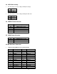
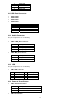
4.11 USB Port Connector
• USB1: CN22
• USB2: CN23
• USB3: CN31
• USB4: CN15
PIN Description
1 +5V
2 DATA-
3 DATA+
4 GROUND
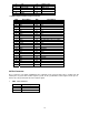
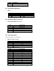
4.12 Audio Connector
The pin assignments are as following.
• CN17: LINE_OUT connector
PIN Description
1 LINE_OUT_L
2,3 LINE_OUT_GROUND
4 LINE_OUT_R
• CN16: MIC_IN connector
PIN Description
1 MIC_IN
2 GROUND
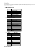
4.13 LED
The pin assignments are as following.
• CN6: LED connector
PIN Description PIN Description
1 POWER LED- 2 POWER LED+
3 HDD LED- 4 HDD LED+
5 LAN LED- 6 LAN LED+
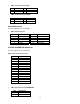
4.14 Power & Reset Button
• CN13: ATX Power button
PIN Description
1 ATX Power button +
2 ATX Power button -
• CN5: Reset button