Installation Guide Anybus BACnet to Modbus Gateway Doc. SP1820 Rev. 1.00 Connecting DevicesTM HALMSTAD • CHICAGO • KARLSRUHE • TOKYO • BEIJING • MILANO • MULHOUSE • COVENTRY • PUNE • COPENHAGEN HMS Industrial Networks Mailing address: Box 4126, 300 04 Halmstad, Sweden Visiting address: Stationsgatan 37, Halmstad, Sweden E-mail: info@hms-networks.com www.anybus.
Important User Information This document provides installation instructions and other relevant information applicable to the Anybus BACnet to Modbus Gateway. Liability Every care has been taken in the preparation of this document. Please inform HMS Industrial Networks AB of any inaccuracies or omissions. The data and illustrations found in this document are not binding. We, HMS Industrial Networks AB, reserve the right to modify our products in line with our policy of continuous product development.
Anybus BACnet to Modbus Gateway Install Guide Doc. SP1820, Rev. 1.
Table of Contents 5 Table of Contents Important User Information . . . . . . . . . . . . . . . . . . . . . . . 3 Overview . . . . . . . . . . . . . . . . . . . . . . . . . . . . . . . . . . . . . . . 6 Specifications . . . . . . . . . . . . . . . . . . . . . . . . . . . . . . . . . . . 8 Electrical . . . . . . . . . . . . . . . . . . . . . . . . . . . . . . . . . . . . . . . . . . . . . . . . . . . . . 8 Communications . . . . . . . . . . . . . . . . . . . . . . . . . . . . . . . . . . . . . . . . . . . .
1. Overview Modbus is a popular network interface commonly used with boiler controllers, variable speed drives, and metering applications, although many of these devices have no BACnet compliance. The Anybus BACnet to Modbus Gateway is used to make Modbus devices appear as individual BACnet devices. The gateway has one 10/100 Mbps Modbus TCP or BACnet/IP Ethernet port, and one opto-isolated Modbus RS-485 serial port for Modbus RTU or Modbus ASCII devices.
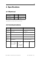
8 2. Specifications 2.1 Electrical Input voltage: Input power: Input frequency: DC 24 V 6W N/A AC 24 V 10 VA 47–63 Hz (Intended for use with Class 2 circuits only.) 2.2 Communications Compliance Protocols supported Data rates Physical layer Max cable length Port connector LED:s Ethernet IEEE 802.3 Modbus TCP BACnet/IP 10 Mbps, 100 Mbps 10BASE-T, 100BASE-TX RS-485 Modbus V1.02 RTU Master ASCII Master 2.4, 4.8 9.6, 19.2, 38.4, 57.6, 76.8, 115.
9 2.2.1 Protocol Compliance BACnet/IP: Modbus TCP: (modbus.org) Modbus Serial: (modbus.org) ASHRAE 135-2004, Annex J, B-ASC Profile Modbus Appl. Protocol Spec. V1.1b, Dec. 28, 2006 Modbus Messaging on TCP/IP Impl. Guide V1.0b, Oct. 24, 2006 Modbus over Serial Line Spec. and Implementation Guide V1.02b, Dec. 20, 2006 2.3 Mounting TS-35 DIN-rail 2.4 Shipping Weight 1 lb. (0.45 kg) 2.5 Regulatory Compliance CE Mark — CFR 47 Part 15 Class A RoHS, UL 508, C22.2 No.
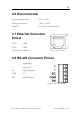
10 2.6 Environmental Operating temperature: 0°C to +60°C Storage temperature: -40°C to +85°C Humidity: 10—95%, non-condensing 2.7 Ethernet Connector Pinout 1 TD+ 3 RD+ 2 TD– 6 RD– (All other pins unused.) Figure 1: RJ-45 socket 2.8 RS-485 Connector Pinout + Signal High – Signal Low SC Signal Common COM 0V SH Shield (Chassis) Figure 2: RS-485 connector Anybus BACnet to Modbus Gateway Install Guide Doc. SP1820, Rev. 1.
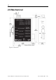
11 2.9 Mechanical Figure 4: Dimensions Anybus BACnet to Modbus Gateway Install Guide Doc. SP1820, Rev. 1.
12 3. Power The Anybus BACnet to Modbus gateway requires 24 VAC or 24 VDC, and draws a commensurate amount of current. The recommended wire gauge is 16–18 AWG. COM is directly connected to zero volts, and the chassis is DC-isolated from zero volts. Input connections are reverse-polarity protected. Figure 5: Power options WARNING: Powering devices can present hazards. Read the following carefully.
13 power supply on all connected devices. In this way all RS-485 transceivers share the same earth reference. Note that the SC pin is signal-common and is not a shield pin. For shield connections, use the SH pin. Far-end external termination is required as shown. Internal termination is not provided. If this is required, use the external termination included with the product. Anybus BACnet to Modbus Gateway Install Guide Doc. SP1820, Rev. 1.
14 For devices that share a power source with this product, see Figure 6 for correct 2-wire bus connections and Figure 7 for correct 3-wire bus connections. Figure 6: 2-wire RS-485 Bus with Shared Power Source Figure 7: 3-wire RS-485 Bus with Shared Power Source Anybus BACnet to Modbus Gateway Install Guide Doc. SP1820, Rev. 1.
15 For devices that do not share power with this product, see Figure 8 for correct 2-wire bus connections and Figure 9 for proper 3-wire bus connections. Figure 8: 2-wire RS-485 Bus with Separate Power Source Figure 9: 3-wire RS-485 Bus with Separate Power Source Anybus BACnet to Modbus Gateway Install Guide Doc. SP1820, Rev. 1.
16 3.1 Limited Power Sources The gateway should be powered by a limited power source complying with the requirements of the National Electric Code (NEC) article 725, or other international codes (SELV) meeting the same intent of limiting the amount of power of the source. Under NEC article 725, a Class 2 circuit is the part of the wiring system between the load side of a Class 2 power source and the connected equipment.
18 4. Hardware & Cabling 4.1 LEDs Power Ethernet RS-485 This LED is green when power is supplied correctly to the unit. L shows green for a 100 Mbps link and yellow for 10 Mbps. Flashes indicate activity. D shows green for a full-duplex link and off for a half-duplex link. Tx flashes green when transmitting RS-485 traffic. Rx flashes green when receiving RS-485 traffic. 4.
19 NOTE: If using shielded cables, these should connect to the chassis at one point only. Wire size may be dictated by electrical codes for the area in which the equipment is being installed. Consult local regulations. In the table above, observe that 10BASE-T segments can use Category 3, 4 or 5 cable, although 100BASE-TX segments must use Category 5 cable. Category 5e cable is highly recommended as the minimum for new installations.
20 In an application where one connection is made to Ethernet and the other to RS-485, the location of the gateway is probably at the end of the RS-485 bus segment, meaning that both bias and termination must be applied to the segment end. The product is shipped with bias and termination disabled by default. This can be changed by using the terminating resistors included in the package. Termination is required if the gateway is to be connected anywhere between the end RS-485 devices.
22 5. Configuration The Anybus BACnet to Modbus Gateway contains an interactive web server, which is accessible from any PC on the local network, and is compatible with recent versions of Internet Explorer or other browsers. The factory default IP address is 192.168.92.68, and the Class C subnet mask is 255.255.255.0 (/24). Figure 10 shows the setup for accessing the RS-485 network using Anybus BACnet to Modbus Gateway, a computer for configuration, and a connection to the RS-485 network.
23 After logging on, the Anybus BACnet to Modbus Gateway Home Page initially appears as shown in Figure 11. To interact with the Anybus BACnet to Modbus Gateway, you must enable Java in your browser. When you access the Anybus BACnet to Modbus Gateway’s first Java applet, you may encounter an additional Java security screen prompting for User ID and Password. These will be the same values as before. After satisfying these prompts, the remaining Java screens should display with no further security prompts.