User Manual Anybus Wireless Bridge Ethernet to WLAN ® Doc. ID HMSI-27-205 Rev. 1.30 Connecting DevicesTM +$/067$' &+,&$*2 .$5/658+( 72.<2 %(,-,1* 0,/$12 08/+286( &29(175< 381( &23(1+$*(1 HMS Industrial Networks Mailing address: Box 4126, 300 04 Halmstad, Sweden Visiting address: Stationsgatan 37, Halmstad, Sweden E-mail: info@hms-networks.com Web: www.anybus.
Important User Information This document is a product guide describing the main use cases for the Anybus Wireless Bridge - Ethernet to WLAN module and how to configure it. It also contains general information about the product. The reader of this document is expected to be familiar with high-level software design, and communication systems in general.
Table of Contents Table of Contents Preface Preface Safety Warnings & Restrictions.............................................................................................................. 5 WARNINGS!............................................................................................................................... 5 RESTRICTIONS......................................................................................................................... 5 About This Document ....................
II - Alternative 1.......................................................................................................................................... 23 Overview ........................................................................................................................................ 23 Set Up the Use Case...................................................................................................................... 23 PC Connected Wirelessly to Wireless Bridge - Alternative 2...
Preface P. Preface P.1 Safety Warnings & Restrictions This equipment is suitable for use in Class I, Division 2, Groups A, B, C and D, or non-hazardous locations only. The combinations of equipment in your own system will be subject to investigation by the local Authority Having Jurisdiction at the time of installation. P.1.1 WARNINGS! EXPLOSION HAZARD! - Do not disconnect equipment unless power has been removed or the area is known to be non-hazardous.
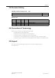
Preface 6 P.4 Document History Summary of Recent Changes (1.20 ... 1.30) Change Removed section 3.13 in chapter 3 Page(s) Revision List Revision 1.00 1.10 1.20 1.30 Date 2011-03-22 2012-04-20 2013-10-09 2015-02-19 Author(s) KaD KaD SDa KeL Chapter(s) All P 3 Description First official release Converted to Framemaker, minor updates and corrections Added safety warnings. Removed section 3.13 in chapter 3 P.
Chapter 1 1. Installation Anybus Wireless Bridge - Ethernet to WLAN Doc.Rev. 1.30 Doc.Id.
Installation 8 1.1 Power The table below shows the typical current at 24 V. Operation Startup Idle Idle, Ethernet Idle + 4xMode LEDs Connecting Connected, Data Connected, Data, Ethernet Connected, Data, Ethernet, 4xMode LEDs Mean (mA) 58.7 69.0 74.2 63.2 63.2 73.4 78.6 Max (mA) 58.8 58.8 69.1 74.3 63.9 64.8 75.5 80.7 1.2 Ethernet Interface The Ethernet interface supports 10/100 Mbps, with both MDI/MDI-X auto crossover and polarity correction. 1.
Chapter 2 2. General Concepts 2.1 Configuration Methods The Wireless Bridge supports four main methods for setting and configuring the module: 1. Smart mode Use the buttons and LED’s on the Wireless Bridge to automatically set up the most common use cases. 2. Web interface An online web interface with the most common settings for the Wireless Bridge. 3. AT commands Connect to the Wireless Bridge over Ethernet using TCP, or directly on Layer 2 and use a terminal such as Hyperterminal to issue AT commands.
General Concepts 10 There are currently 12 different modes available: Mode 1 Description Enable DHCP server LEDs A 2 Reset to factory defaults. This will reset the entire configu- B ration to factory defaults. 3 Reset IP settings to factory defaults. This will only reset the A + B IP settings to factory defaults. 4 Wait for Automatic configuration, ad-hoc mode. C 5 Initiate Automatic configuration, ad-hoc mode. A+C 6 Wait for Automatic configuration with Profinet optimizations, ad-hoc mode.
General Concepts 11 An example of the web interface is shown below: Anybus Wireless Bridge - Ethernet to WLAN Doc.Rev. 1.30 Doc.Id.
General Concepts 12 2.2.2 Reset to Factory Defaults It is possible to reset to the factory default settings in 4 different ways: • Enter and confirm SMART mode 2. • Issue AT&F. • Hold the Mode button while the Wireless Bridge is starting. Note: Ensure that the Ethernet cable is disconnected, and that any firmware update program has been stopped. • Press the Restore Device button in the AT-commands section. 2.2.
General Concepts 13 2.2.5 WLAN Security The Wireless Bridge supports various authentication and encryption methods.
General Concepts 14 Key Management For WEP64 and WEP128, shared keys can be entered in all four possible slots made available by the AT*AGFPWI Write Encryption/Authentication Key (with Index) command. However, for LEAP, PEAP and WPA/WPA2 PSK, the password or PSK must be entered in the key slot with index 1 (one). This key must also be the one currently set as active by the AT*AGAFP Active Encryption/Authentication Key command.
Chapter 3 3. Supported Use Cases 3.1 Two Wireless Bridges Connected as Ethernet Bridge - Alternative 1 3.1.1 Overview This use case describes two Wireless Bridges connected in Ethernet Bridge mode. Multiple Ethernet devices on each side of the module are supported. The Ethernet data is bridged through a UDP tunnel and ad-hoc mode is used. 3.1.2 Set Up the Use Case This use case can be set up using the SMART button. 1. Power on the first device and enter SMART configuration mode 4. 2.
Supported Use Cases 16 Should the predefined IP addresses already be in use on your network, it may be necessary to configure the setup manually: 1. Power on the first Wireless Bridge and enter the web configuration. See “Using the Web Configuration Interface” on page 10. 2. Enter the required IP Address (IP_ADDR1), Netmask and Default Gateway. DHCP should be turned off. Click "Write Network Settings". Note: The IP address must be selected to avoid IP conflicts. 3.
Supported Use Cases 17 3.2 Two Wireless Bridges Connected as Ethernet Bridge - Alternative 2 3.2.1 Overview This use case describes two Wireless Bridges connected in Ethernet Bridge mode. Multiple Ethernet devices on each side of the module are supported. The Ethernet data is bridged through an UDP tunnel, and Managed (Infrastructure) mode is used. 3.2.2 Set Up the Use Case This use case can be set up using the SMART button.
Supported Use Cases 18 Alternative 2 - Manual Configuration This example show the settings when SMART mode 8 (Wireless Bridge 1) and 9 (Wireless Bridge 2) are used. In addition to the values below, the Network Name (SSID) and security must be configured according to the settings in the Access Point (AP).
Supported Use Cases 19 3.3 Two Wireless Bridges Connected as Ethernet Bridge - Alternative 3 3.3.1 Overview This use case uses two Wireless Bridges connected in Ethernet Bridge mode. Here, one of the modules is connected to a wired network and it does NOT use the wireless connection. Managed (infrastructure) mode is used. 3.3.2 Set Up the Use Case This use case can be set up by the SMART button.
Supported Use Cases 20 Alternative 2 - Manual Configuration This example shows the settings when SMART mode 8 (Wireless Bridge 1) and 10 (Wireless Bridge 2) are used. In addition to the values below, the network SSID and security must be configured according to the settings in the Access Point (AP) on Wireless Bridge 1.
Supported Use Cases 21 3.4 Two Wireless Bridges in Client Mode - Alternative 1 3.4.1 Overview This use case describes two Wireless Bridges connected in Client mode. Only one Ethernet device can be connected to each of the modules. This use case will have higher performance than using the Ethernet Bridging case (no encapsulation of the Ethernet packages required). 3.4.2 Set Up the Use Case This use case can be set up by using the SMART button and supports ad-hoc mode only. 1. Power on the first module.
Supported Use Cases 22 3.5 Two Wireless Bridges Connected in Client Mode Alternative 2 3.5.1 Overview This use case describes two Wireless Bridges connected in Client mode. Only one Ethernet device can be connected to each of the modules. The Wireless Bridge is connected to a WLAN Access Point that allows the use of Managed (infrastructure) mode with higher performance as a result. 3.5.2 Set Up the Use Case Both modules must operate in Client or Multiclient mode in this use case. 1.
Supported Use Cases 23 3.6 PC Connected Wirelessly to Wireless Bridge - Alternative 1 3.6.1 Overview In this use case only ONE Ethernet device is connected to the Wireless Bridge. The PC is used to access the Ethernet device, using any Ethernet-based protocol, e.g. a built-in web interface or an Ethernet based communication protocol e.g. Modbus-TCP. 3.6.2 Set Up the Use Case The Wireless Bridge must operate in Client Mode in this use case. 1. Connect a PC to the Wireless Bridge.
Supported Use Cases 24 3.7 PC Connected Wirelessly to Wireless Bridge - Alternative 2 3.7.1 Overview In this use case, only ONE Ethernet device is connected to the Wireless Bridge. The PC is used to access the Ethernet device, using any Ethernet-based protocol, e.g. a built-in web interface or an Ethernet based communication protocol, e.g. Modbus-TCP.
Supported Use Cases 25 3.8 Multiple Ethernet Devices Connected in Client Mode - Alternative 1 3.8.1 Overview Three or more Wireless Bridges connected in an ad-hoc network. This use case requires Client mode. 3.8.2 Set Up the Use Case The Wireless Bridge must operate in Client Mode in this use case. 1. Connect a PC to each of the Wireless Bridges. See section “Using the Web Configuration Interface” on page 10 for more information on how to connect to the Wireless Bridge. 2.
Supported Use Cases 26 3.9 Multiple Ethernet Devices Connected in Client Mode - Alternative 2 3.9.1 Overview Three or more Wireless Bridges connected through a WLAN Access Point. This use case requires Client mode. In this case the Wireless Bridges are connected to each other via a WLAN Access Point that allows the use of Managed (infrastructure) mode, resulting in higher performance. 3.9.2 Set Up the Use Case All Wireless Bridges must operate in Client Wireless Mode in this use case. 1.
Supported Use Cases 27 3.10 One or More Wireless Bridges Connected to a Wired Infrastructure through WLAN 3.10.1 Overview In this use case the Wireless Bridges are used to connect to a wired Ethernet infrastructure using a standard WLAN access point. Other WLAN devices can, of course, be connected to the same access point, assuming they share the same networking parameters as the Wireless Bridges. 3.10.2 Set Up the Use Case All Wireless Bridges must operate in Client Mode in this use case. 1.
Supported Use Cases 28 3.11 External WLAN Client Connected to a Wireless Bridge 3.11.1 Overview In this use case, some other WLAN client is connected to a Wireless Bridge that in turn is connected to an Ethernet device. 3.11.2 Set Up the Use Case The Wireless Bridge must operate in Client Mode in this use case. 1. Connect a PC to the Wireless Bridges. See section “Using the Web Configuration Interface” on page 10 for more information on how to connect to the Wireless Bridge. 2.
Supported Use Cases 29 3.12 Multiclient Mode 3.12.1 Overview Multiclient mode is used when there is a need to have several devices (3 and 4 in figure above) behind the Wireless Bridge that communicates with 1 and/or 2. The restriction is that only one device (3 or 4 in the example) can use Layer-2 communication, while the others need to use the IP layer. The Wireless Bridge must also be configured on the same IP subnet as the other devices.
Appendix 4 4. Legal and Regulatory 4.1 ICC and FCC Compliance IC Compliance Operation is subject to the following two conditions: 1. This device may not cause harmful interference 2.
Legal and Regulatory 31 Ad-hoc Frequencies When operating under the definition of a client in 47 CFR §15.202 is preconfigured to use the most restrictive regulatory domain. For this reason the available operating frequency range is limited to channel 1 - 11 (2412 - 2462 MHz) for IEEE802.11b/g. For IEEE802.11a the available operating frequency range is limited to channels 36 - 48 (5180 - 5240 MHz).
Legal and Regulatory 32 4.3 Licenses This product contains software under the following licenses: /* * Copyright (c) 2001-2004 Swedish Institute of Computer Science. * All rights reserved. * * Redistribution and use in source and binary forms, with or without modification, * are permitted provided that the following conditions are met: * * 1. Redistribution of source code must retain the above copyright notice, * this list of conditions and the following disclaimer. * 2.