
Instructions


Connector Pin Assignments 70
Doc: HMSI-27-306, Rev. 3.11Anybus Communicator PROFIBUS User Manual
A.4 Subnetwork Interface
A.4.1 General Information
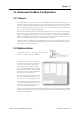
The subnetwork interface provides for RS232, RS422 and RS485 communications. Depending on the
configuration specified in the Anybus Configuration Manager, different signals are activated in the sub-
network connector.
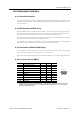
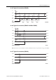
A.4.2 Bias Resistors (RS485 Only)
When idle, RS485 enters an indeterminate state, which may cause the serial receivers to pick up noise
from the serial lines and interpret this as data. To prevent this, the serial lines should be forced into a
known state using pull-up and pull-down resistors, commonly known as bias resistors.
The bias resistors form a voltage divider, forcing the voltage between the differential pair to be higher
than the threshold for the serial receivers, typically >200 mV.
Note that bias resistors shall only be installed on one node; installing bias resistors on several nodes may
compromise the signal quality on the network and cause transmission problems.
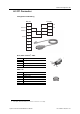
A.4.3 Termination (RS485 & RS422 Only)
To avoid reflections on the serial lines, it is important to properly terminate the subnetwork by placing
termination resistors between the serial receivers near the end nodes.
The resistor value should ideally match the characteristic impedance of the cable, typically 100–120 Ω.
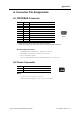
A.4.4 Connector Pinout (DB9F)
Pin Description RS232 RS422 RS485 RS485
1 +5 V Output(100 mA max)
2 RS232 Rx
3 RS232 Tx
4 (reserved)
5
Signal Ground
a
a. Connecting this signal directly to Protective Earth (PE) of other nodes may, in case of grounding loops etc., cause
damage to the on-board serial transceivers. It is therefore generally recommended to connect it only to Signal
Ground (if available) of other nodes.
6 RS422 Rx +
7 RS422 Rx -
8 RS485 + / RS422 Tx+
9 RS485 - / RS422 Tx-
(housing) Cable Shield
96
15 (female)