
Instructions


Anybus Communicator - PROFIBUS DP Interface Installation Sheet
www.anybus.comSP0632, rev. 1.20, Mar 2015
1
3
5
2
4
6
A
B
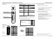
Configuration Switches
PROFIBUS Connector
LED Indicators
Module Front LED Indicators
LED no Indication Meaning
1 (Online) Green
Off
Online
Not online
2 (Offl ine) Red
Off
Offl ine
Not offl ine
3 (Not used) - -
4 (Fieldbus Diagnostics) Off
Red, fl ashing 1Hz
Red, fl ashing 2Hz
Red, fl ashing 4Hz
No diagnostics present
Confi guration error
User parameter data error
Initialization error
5 (Subnet Status) Flashing green
Green
Red
Running, but one or more transaction errors
Running
Transaction error/timeout or subnet stopped
6 (Device Status) Off
Alternating red/green
Green
Flashing green
Red
Flashing red
Power off
Invalid or missing confi guration
Initializing
Running
Bootloader mode
Note the fl ash sequence pattern and contact
the HMS support department
1
9
5
6
1
2
4
1
Bottom View
Subnetwork Connector
Pin no. Description
1 +5V OUT
2 RS232 Rx
3 RS232 Tx
4NC
5 Signal GND
6 RS422 Rx+
7 RS422 Rx-
8 RS485+ / RS422 Tx+
9 RS485- / RS422 Tx-
PC Connector:
1. GND
2. GND
3. RS232 Rx
4. RS232 Tx
Power:
1. +24 V DC
2. GND
Accessories Checklist
The following items are required for installation:
• Anybus Communicator Resource CD (Includes confi guration
software, manuals, GSD fi le and application notes)
• RS232 confi guration cable
• Subnetwork connector
• PROFIBUS network cable and connector (not included)
Installation and Startup Summary
• Mount the Communicator on the DIN-rail.
• Connect the Communicator to the PROFIBUS network.
• Connect the Communicator to the subnetwork.
• Power on the Communicator (+24 V DC).
• Connect the confi guration cable between the Communicator
and the PC containing the Anybus Confi guration Manager
software (ACM).
• Confi gure the module using ACM.
• Include the Anybus Communicator GSD fi le in the
PROFIBUS confi guration tool.
• Confi gure and start the PROFIBUS network.
Further information and documents about this product can be
found at the product pages on www.anybus.com.
PROFIBUS Connector
Pin no Description
1 Shield
3 B-line
4RTS
5 GND bus
6 +5V bus out
8 A-line
2, 7, 9 NC
9 6
1 5 (female)
Confi guration Switches
Set the PROFIBUS node address by using the switches as follows:
Node address = (switch B * 10) + (switch A * 1)
Example:
Setting node address 42
A
B
Switch A
Switch B
2
4