Anybus® Wireless Bolt IoT™ USER MANUAL SCM-1202-139 1.
Important User Information Disclaimer The information in this document is for informational purposes only. Please inform HMS Networks of any inaccuracies or omissions found in this document. HMS Networks disclaims any responsibility or liability for any errors that may appear in this document. HMS Networks reserves the right to modify its products in line with its policy of continuous product development.
Table of Contents 1 2 3 4 5 6 Page Preface ................................................................................................................................ 3 1.1 About This Document .......................................................................................................3 1.2 Document Conventions .....................................................................................................4 1.3 Trademarks.......................................................
7 8 9 Verify Operation................................................................................................................ 31 7.1 System Settings and Network Connection........................................................................... 31 7.2 Ethernet LED Status Indication ......................................................................................... 32 Maintenance...........................................................................................................
Preface 3 (46) 1 Preface 1.1 About This Document This manual describes how to install and configure Anybus Wireless Bolt IoT. For additional documentation and software downloads, FAQs, troubleshooting guides and technical support, please visit www.anybus.com/support. Anybus® Wireless Bolt IoT™ User Manual SCM-1202-139 1.
Preface 1.2 4 (46) Document Conventions Numbered lists indicate tasks that should be carried out in sequence: 1. First do this 2. Then do this Bulleted lists are used for: • Tasks that can be carried out in any order • Itemized information ► An action → and a result User interaction elements (buttons etc.) are indicated with bold text. Program code and script examples Cross-reference within this document: Document Conventions, p. 4 External link (URL): www.hms-networks.
Safety 5 (46) 2 Safety 2.1 General Safety Instructions Caution This equipment emits RF energy in the ISM (Industrial, Scientific, Medical) band. Make sure that all medical devices used in proximity to this equipment meet appropriate susceptibility specifications for this type of RF energy. This equipment is recommended for use in both industrial and domestic environments. For industrial environments it is mandatory to use the functional earth connection to comply with immunity requirements.
Preparation 6 (46) 3 Preparation 3.1 Support and Downloads For additional documentation and software downloads, FAQs, troubleshooting guides and technical support, please visit www.anybus.com/support. Have the product article number available, to search for the specific product page. You find the product article number on the Wireless Bolt IoT product housing. 3.
Preparation 3.5 7 (46) Placement For optimal reception, cellular devices should not be confined in buildings made of concrete or metal, without windows. To avoid interference, a minimum distance of 50 cm between cellular devices should be observed. At least 20 cm separation distance between the device and the user’s body must be maintained at all times. 3.6 Firewall and Routing There are routing options set for the system.
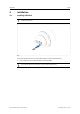
Installation 8 (46) 4 Installation 4.1 Installing SIM Card Supported SIM card types are Nano SIM for IoT and M2M, for data communication, as well as standard mobile phone Nano SIM. Fig. 1 To connect Wireless Bolt IoT to a cellular data network, install a cellular SIM card: 1. Insert a SIM card into the Wireless Bolt IoT SIM card holder. Ensure that the SIM card contact surface is facing towards the Ethernet port. Anybus® Wireless Bolt IoT™ User Manual SCM-1202-139 1.
Installation 4.2 9 (46) Mechanical Installation Placement • The device is intended to be mounted on top of a machine or cabinet through an M50 (50.5 mm) hole using the included sealing ring and nut. • The top mounting surface, in contact with the sealing, must be flat with a finish equivalent to Ra 3.2 or finer and cleaned and free from oils and greases. • For optimal reception, cellular devices require a zone around them clear of objects that could obstruct or reflect the signal.
Installation 4.3 10 (46) Connecting to Ethernet/Power Over Ethernet (PoE) Before You Begin Connecting the Wireless Bolt IoT to PoE and DC power simultaneously may result in a current loop that could damage both the power sources and the Wireless Bolt IoT. Ensure to use only one of the power connections at a time. Shielded or unshielded Ethernet cables may be used. Wireless Bolt IoT is designed to comply with PoE class 0 (37-57 VDC, max 0.35 A), according to IEEE 802.3. Procedure Fig. 3 1.
Installation 4.4 11 (46) Connecting to Power Before You Begin Connecting power with reverse polarity or using the wrong type of power supply may damage the equipment. Make sure that the power supply is connected correctly and of the recommended type. When Wireless Bolt IoT is powered via the power connector, Functional Earth (FE) must be connected.
Installation 12 (46) Procedure Fig. 5 1. Connect Wireless Bolt IoT Power connector to a power supply. 2. Connect Wireless Bolt IoT Power connector to Functional Earth (FE). Power connector, 3-pin terminal block Pin 2 Function + - 3 Functional Earth (FE) 1 Anybus® Wireless Bolt IoT™ User Manual 11–33 VDC SCM-1202-139 1.
Installation 13 (46) To Do Next ► Connect the Wireless Bolt IoT to Ethernet. Fig. 6 Connecting the Wireless Bolt IoT to PoE and DC power simultaneously may result in a current loop that could damage both the power sources and the Wireless Bolt IoT. Ensure to use only one of the power connections at a time. Fig. 7 Anybus® Wireless Bolt IoT™ User Manual SCM-1202-139 1.
Configuration 14 (46) 5 Configuration 5.1 Connecting to PC and Power When configuring Wireless Bolt IoT it must be connected to a PC. Fig. 8 1. Connect the Wireless Bolt IoT Ethernet port to your PC. 2. Connect the Wireless Bolt IoT Power connector to a power supply. Anybus® Wireless Bolt IoT™ User Manual SCM-1202-139 1.
Configuration 5.2 15 (46) PC IP Address Setting By default, the Wireless Bolt IoT internal DHCP server is enabled. To avoid interference, keep only one DHCP server enabled on the network. Wireless Bolt IoT default IP address is 192.168.0.98. To find Wireless Bolt IoT on your network, choose one of the following methods: Set a Static IP Address on Your PC On the PC accessing the Wireless Bolt IoT built-in web interface: 1.
Configuration 5.3 16 (46) Accessing Wireless Bolt IoT Web Interface The Wireless Bolt IoT built-in web interface can be accessed from standard web browsers. Before installing the Wireless Bolt IoT on a network, change the Wireless Bolt IoT default username and password. The Wireless Bolt IoT comes with a default username and password. The default username is admin. Written in lowercase letters. You find the default password on the Wireless Bolt IoT product housing.
Configuration 5.4 17 (46) Web Interface Overview The Wireless Bolt IoT built-in web interface is used to configure the Wireless Bolt IoT system settings as well as for diagnostics and maintenance. The System Overview page shows the current settings and network connection status. Fig. 11 Wireless Bolt IoT built-in web interface, example A. System Overview Shows the current settings and network connection status B. Left sidebar menu C.
Configuration 5.5 18 (46) Save and Reboot Cancel Changes Fig. 12 If you need to cancel the changes you have made to the settings: 1. In the left sidebar menu, click Cancel All Changes. To restore settings, refer to Restore Settings, p. 36. Apply Changes Fig. 13 To apply changes: 1. In the left sidebar menu, click Save and Reboot. → 5.6 Wireless Bolt IoT restarts for the changes to take effect. Factory Default Settings Wireless Bolt IoT comes with the following factory default settings.
Configuration 5.7 19 (46) Ethernet Settings On the Ethernet Settings page: Fig. 14 Default, IP Settings with Internal DHCP Server Enabled IP Settings IP Address The default Wireless Bolt IoT static IP address is 192.168.0.98. When you change the IP address: 1. Click Save and Reboot to reboot Wireless Bolt IoT. → 2. In your web browser, enter the new IP address and press Enter. → 3. Wireless Bolt IoT reboots for the setting to take effect. The built-in web interface login screen appears.
Configuration 20 (46) Internal DHCP Server By default, the Wireless Bolt IoT internal DHCP server is enabled. To avoid interference, keep only one DHCP server enabled on the network. The DHCP server is only enabled on the LAN interface. By default, Internal DHCP Server is set to Enabled. → This means that the IP address settings are set automatically by the Wireless Bolt IoT internal DHCP server.
Configuration 5.8 21 (46) Cellular Settings When you are going to connect Wireless Bolt IoT to a cellular network, make sure that you have installed a SIM card in Wireless Bolt IoT SIM card holder. Refer to Installing SIM Card, p. 8. 5.8.1 Network Settings Before You Begin • When using the LTE-M technology, it can take several hours for a device to get connected to the cellular network. • It can take up to one hour to connect to a LTE NB1 network.
Configuration 5.8.2 22 (46) APN Settings On the Cellular Settings page: Automatic APN Assignment An APN automatically derived from SIM card identification may not give full access to the cellular network. Follow your network operator's guidelines. By default, Wireless Bolt IoT is set to automatically search for the SIM card APN setting. If a general APN string is available for the network operator, it will be set as the APN Assignment.
Configuration 23 (46) Manual APN Assignment You can set the APN Assignment manually. Ensure that you have the APN supplied by your carrier available. Fig. 17 1. APN example Enter the APN in the APN field. APN Authentication By default, APN Authentication is set to No. When enabled, PAP method is used. APN Authentication is to be configured only if your carrier has setup APN (Access Point Name) with username and password.
Configuration 5.8.3 24 (46) Lock Configuration When configuration is locked, you can still access and use the Wireless Bolt IoT built-in web interface but the settings can not be configured. On the System page: Fig. 19 Restore Settings from a backup file To lock the configuration: 5.8.4 1. Click Config Lock. 2. To confirm lock configuration, click OK. Unlock Configuration To unlock configuration, do a factory reset using the Wireless Bolt IoT Reset button. Refer to Reset and Recovery, p. 42.
Configuration 5.9 25 (46) NAT/Port Forward Settings NAT/Port forward is used to allow incoming traffic from an external network access to a device IP address on the internal network. The Source Filter setting is used to prevent unauthorized traffic on the local network. By default, Incoming Traffic NAT 1:1 is set to Disabled. All incoming traffic from the external network is rejected. Procedure On the NAT/Port Forward Settings page: Fig. 20 To configure the NAT 1:1 settings: 1.
Configuration 26 (46) 5.10 Setting Up with REST Commands 5.10.1 How To Use REST Commands For information about the supported REST commands and how to use them, refer to the REST Commands Reference Guide at www.anybus.com/support. 5.10.2 Use/Test REST Commands From a Web Browser For information about the supported REST commands, refer to the REST Commands Reference Guide at www.anybus.com/support. Procedure 1. Setup the Wireless Bolt IoT as an internet router.
Configuration Examples 27 (46) 6 Configuration Examples 6.1 Setting Up Wireless Bolt IoT as an Internet Router Use Wireless Bolt IoT as an internet router to connect machines, controllers or other devices to internet. Before You Begin Wireless Bolt IoT comes with a default username and password. The default username is admin. Written in lowercase letters. You find the default password on the Wireless Bolt IoT product housing. Wireless Bolt IoT default IP address is 192.168.0.98.
Configuration Examples 28 (46) 6. Configure the Ethernet Settings, IP address and internal DHCP server settings. 7. Verify that the APN Settings are correct. You can adjust the settings manually. 8. In the left sidebar menu, click Save and Reboot. → 9. Wireless Bolt IoT automatically reboots for the settings to take effect On the System Overview page, verify that the cellular Data Connection has status Yes. Result Wireless Bolt IoT should now be connected to internet.
Configuration Examples 29 (46) Connecting Devices Fig. 23 Connecting a device to internet: 1. Connect an Ethernet cable between Wireless Bolt IoT and the device. 2. Verify that the device is connected to internet. Anybus® Wireless Bolt IoT™ User Manual SCM-1202-139 1.
Configuration Examples 6.2 30 (46) Setting Up Wireless Bolt IoT with ULPM REST Command The Wireless Bolt IoT variant for the US market does not support the ULPM REST Command. You can use Wireless Bolt IoT as an internet router with Ultra Low Power Mode (ULPM) to save electrical energy. Devices using other power sources than grid connected power, such as devices powered by batteries and/or solar panels, benefit from using ULPM.
Verify Operation 31 (46) 7 Verify Operation 7.1 System Settings and Network Connection On the System Overview page, verify the settings and network connection status. Fig. 24 Example, Verify Settings and Network Connection Data Connection Data Connection status Yes is picked up from the underlying system and is not tested for data transfer. The Wireless Bolt IoT modem may get a control connection, but once data is sent the connection is terminated immediately.
Verify Operation 7.2 32 (46) Ethernet LED Status Indication Fig. 25 RJ45 LED indicators LED A – LINK/ACTIVITY Function Off Yellow No Ethernet link 10 Mb/s Ethernet link established Yellow, flashing 10 Mb/s Ethernet activity Green 100 Mb/s Ethernet link established Green, flashing 100 Mb/s Ethernet activity LED B – STATUS Off Function No power Blue Purple Connected on LTE-M Connected on LTE NB1 Blue, slow blink Connected on GSM.
Maintenance 33 (46) 8 Maintenance 8.1 Firmware Update Update Wireless Bolt IoT firmware. The configuration settings are not affected when updating firmware. ► Download the firmware update file from www.anybus.com/support. ► Connect Wireless Bolt IoT to your computer, refer to Connecting to PC and Power, p. 14. On the Firmware Update page: Fig. 26 Firmware Update 1. Click Choose File. 2. In the Open dialog box, browse to and select the firmware update file and click Open. 3.
Maintenance 34 (46) → The progress bar, Transferring file, indicates the progress of the file transfer. Status messages show the progress of the firmware update stages. → When the file transfer is finished, the progress bar turns green. Reboot: Fig. 28 → Firmware Update When the firmware update is finished, Wireless Bolt IoT automatically reboots for the updates to take effect. The progress bar, Waiting for reboot, indicates the progress.
Maintenance 8.2 35 (46) Set Administrator Password Before installing Wireless Bolt IoT on a network, change the default administrator password. Wireless Bolt IoT comes with a default username and password. The default username is admin. Written in lowercase letters. You find the default password on the Wireless Bolt IoT product housing. On the System Settings page, Admin Password pane: Fig. 29 Set Admin Password 1. In the Password field, enter your preferred admin password. 2.
Maintenance 8.3.2 36 (46) Restore Settings When you restore settings from a backup file, all the current settings are overwritten by the settings loaded from the backup file. On the System page: Fig. 31 Restore Settings from a backup file Restore settings from a backup file: 1. Click Choose file. 2. Browse to and select your backup file 3. Click Load. → Wireless Bolt IoT reboot automatically, for the settings loaded from the backup file to take effect.
Maintenance 8.4 37 (46) Reboot System On the System page: Fig. 32 1. 2. Reboot System If you have made any changes to the settings, you are prompted to click: – Save, to save the settings. – Cancel, to reboot the system without applying changes. To reboot the system, press Reboot System. Anybus® Wireless Bolt IoT™ User Manual SCM-1202-139 1.
Troubleshooting 38 (46) 9 Troubleshooting 9.1 Logs The System Log contain useful information for troubleshooting issues that may occur in the system. The Log file contains additional information, such as messages from the kernel, drivers, init scripts, services and applications (not originating from HMS). Before contacting support for assistance, it is suggested that you save the System Log file and then add it as an attachment when you create the support ticket. On the Logs page: Fig. 33 1.
Troubleshooting 9.2 Diagnostics Fig. 34 9.2.1 39 (46) Diagnostics Cellular Diagnostics Monitor Signal Strength and Quality You can use the diagnostics information when planning the installation of Wireless Bolt IoT. If Wireless Bolt IoT are going to be placed in a fixed installation and there are several possible locations to choose between, it is viable to monitor the signal strength and quality in the intended locations.
Troubleshooting 9.2.3 40 (46) Network Diagnostics If Anybus Wireless Bolt IoT is installed on a private cellular network, the methods are limited according to the restrictions of the private network. The methods are useful when evaluating the connection on the cellular network. Complete the evaluation by performing tests from the connected device on the LAN network. To get reliable network diagnostics results, large amounts of data may be used.
Troubleshooting 3. 41 (46) To Perform Action, click Start. → The request is sent to the target. → When the target response returns, a message appears. Fig. 35 Example, Ping response message from target 8.8.8.8 Fig. 36 Example, Nslookup response message from target www.anybus.com Fig. 37 Example, Wget response message from target Speedtest Anybus® Wireless Bolt IoT™ User Manual SCM-1202-139 1.
Troubleshooting 42 (46) 9.3 Reset and Recovery 9.3.1 Reset Button Fig. 38 Reset button The Reset button is located on the bottom of the Wireless Bolt IoT. 9.3.2 Factory Reset Factory Reset will result in the loss of all configuration settings and logs. Make sure that the Wireless Bolt IoT is connected to power. Factory Reset Using the Reset Button 1. Use a pointed object (such as a ballpoint pen) to press and hold the Reset button for >10 seconds and then release it.
Troubleshooting 43 (46) Factory Reset Using the Web Interface On the System page: Fig. 39 Factory Reset 1. Click Factory Reset. 2. To confirm factory reset, click OK. Result → Wireless Bolt IoT is reset to the factory default settings. Anybus® Wireless Bolt IoT™ User Manual SCM-1202-139 1.
Technical Data 44 (46) 10 Technical Data 10.1 Technical Specifications Order code AWB1000 AWB1001 Color Black White top and black base Operating temperature Shadow: -40 to +65 °C Direct sunlight: -40 to +45 °C Shadow: -40 to +65 °C Direct sunlight: -40 to +65 °C Host interface RJ45 Ethernet 10/100 Mbit/s, PoE Storage temperature -40 to +85 °C Humidity compability EN 600068-2-78: Damp heat, +40 °C, 90% (non-condensing). Vibration Refer to datasheet at www.anybus.com/support.
This page intentionally left blank
last page © 2020 HMS Industrial Networks Box 4126 300 04 Halmstad, Sweden info@hms.se SCM-1202-139 1.