Anybus® Wireless Bolt™ USER MANUAL SCM-1202-007 2.
Important User Information Liability Every care has been taken in the preparation of this document. Please inform HMS Industrial Networks AB of any inaccuracies or omissions. The data and illustrations found in this document are not binding. We, HMS Industrial Networks AB, reserve the right to modify our products in line with our policy of continuous product development.
Table of Contents 1 Page Preface ............................................................................................................................... 3 1.1 About This Document.....................................................................................................3 1.2 Related Documents .......................................................................................................3 1.3 Document history.....................................................................
This page intentionally left blank
Preface 3 (30) 1 Preface 1.1 About This Document This manual describes how to install and configure Anybus Wireless Bolt. For additional related documentation and file downloads, please visit the Anybus support website at www.anybus.com/support. 1.2 1.3 1.4 Related Documents Document Anybus Wireless Bolt Installation Guide Author HMS Document ID SCM-1202-006 (SP2139) Anybus Wireless Bolt AT Commands Reference HMS SCM-1202-004 Document history Version Date Description 1.0 1.
Preface 1.5 4 (30) Conventions Ordered lists are used for instructions that must be carried out in sequence: 1. First do this 2. Then do this Unordered (bulleted) lists are used for: • Itemized information • Instructions that can be carried out in any order ...and for action-result type instructions: ► This action... ➨ leads to this result Bold typeface indicates interactive parts such as connectors and switches on the hardware, or menus and buttons in a graphical user interface.
Product Description 2 5 (30) Product Description Anybus Wireless Bolt provides wireless communication over WLAN and/or Bluetooth® to wired networks.
Installation 3 6 (30) Installation Caution This equipment emits RF energy in the ISM (Industrial, Scientific, Medical) band. Make sure that all medical devices used in proximity to this device meet appropriate susceptibility specifications for this type of RF energy. This product is recommended for use in both industrial and domestic environments. For industrial environments it is mandatory to use the functional earth connection to comply with immunity requirements.
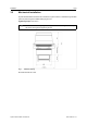
Installation 3.2 7 (30) Mechanical Installation Anybus Wireless Bolt is intended to be mounted on top of a machine or cabinet through an M50 (50.5 mm) hole using the included sealing ring and nut. Tightening torque: 5 Nm ±10 % Make sure that the sealing ring is correctly placed in the circular groove in the top part of the housing before tightening the nut. Fig. 1 Installation drawing All measurements are in mm. Anybus® Wireless Bolt™ User Manual SCM-1202-007 2.
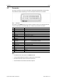
Installation 3.3 8 (30) Connector The 18-pin connector is common for all models of the Anybus Wireless Bolt. Some pins may have a different function depending on model. Unused pins should not be connected. Fig. 2 Connector The location of the RESET button can be used as a reference for the pin numbering when the connector is attached to the Wireless Bolt. Pin 1 will be the pin closest to the button.
Installation 3.4 9 (30) Cabling To make an Ethernet connector cable for the Anybus Wireless Bolt: Fig. 3 Ethernet cable 1. Cut off one of the connectors on a standard Cat5e or Cat6 Ethernet cable. 2. Strip off about 40 mm (1½ inch) of the cable jacket and untwist the orange, orange/white, green and green/white wires. The other wires will not be used. 3. Strip off about 7 mm (¼ inch) of the isolation on each wire. 4.
Configuration 10 (30) 4 Configuration 4.1 General Anybus Wireless Bolt should normally be configured via the web interface. Parameters can be set individually or using one of the pre-configured Easy Config modes. Advanced configuration can be carried out by issuing AT (modem) commands through the web interface or over a Telnet or RAW TCP connection to port 8080. See AT Commands, p. 20. The web interface is accessed by pointing a web browser to the IP address of the Wireless Bolt.
Configuration 11 (30) 4.2 Web Interface 4.2.1 System Overview Fig. 5 System Overview page The Save and Reboot button will become enabled If the unit needs to be restarted for a parameter change to come into effect. To go back to the current configuration without saving changes, click on Cancel All Changes. Anybus® Wireless Bolt™ User Manual SCM-1202-007 2.
Configuration 4.2.2 12 (30) Easy Config Fig. 6 Easy Config page To activate an Easy Config mode, select it from the dropdown menu and click on Set.
Configuration 4.2.3 13 (30) Network Settings Fig. 7 Network Settings page IP Assignment Select static or dynamic IP addressing (DHCP) IP Address Static IP address for the unit Subnet Mask Subnet mask when using static IP Default Gateway Default gateway when using static IP Internal DHCP Server Disabled: No internal DHCP functionality DHCP Relay Enabled: The unit can receive a DHCP request on one interface and resend it to a DHCP server located on one of the other interfaces.
Configuration 4.2.4 14 (30) WLAN Settings – Client Mode Fig. 8 WLAN Settings – Client Enable Enable/disable the WLAN interface. Operating Mode Choose if the unit should operate as a WLAN Client or Access Point. If Access Point is selected, additional parameters will be visible. Channel Bands Choose to scan for networks on either the 2.4 GHz or 5 GHz channel band, or on both (default). The unit must be rebooted to enable the new setting. The unit can be configured to scan on both the 2.
Configuration 15 (30) Fig. 9 WLAN Client – Advanced Settings Advanced Settings Bridge Mode Layer 2 tunnel = All layer 2 data will be bridged over WLAN. This mode should be used when multiple devices on both sides of an Ethernet network bridge must be able to communicate via WLAN (many-to-many). Layer 2 cloned MAC only = Layer 2 data from only a single MAC address (specified below) will be bridged over WLAN (many-to-one). Layer 3 IP forward (default) = IP data from all devices will be bridged over WLAN.
Configuration 4.2.5 16 (30) WLAN Settings – Access Point Mode Fig. 10 WLAN Settings – Access Point The following settings are specific when Access Point mode is selected. Network (SSID) Enter an SSID (network name) for the Wireless Bolt. If this entry is left blank, the unit will generate an SSID which includes the last 6 characters of the MAC ID. Authentication Mode Select the authentication/encryption mode to use for the access point.
Configuration 4.2.6 17 (30) Bluetooth Settings – General Fig. 11 Bluetooth Settings Enable Enable/disable the Bluetooth interface. Operating Mode PANU (Client) = The unit will operate as a Bluetooth PAN (Personal Area Network) User device. It can connect to another single Bluetooth PANU device or to a Bluetooth Network Access Point. NAP (Access Point) = The unit will operate as a Bluetooth Network Access Point. It can connect to up to 7 Bluetooth PANU devices.
Configuration 4.2.7 18 (30) Bluetooth Settings – Mode Specific Fig. 12 Bluetooth Settings PANU mode only Scan for Devices Scans the network for discoverable Bluetooth devices. To connect to a device, select it from the dropdown menu when the scan has completed. Connect To Used when connecting manually to a NAP or PANU device. Connection Scheme Choose whether to select a Bluetooth device by MAC address or name when connecting manually.
Configuration 4.2.8 19 (30) Firmware Update Fig. 13 Firmware Update Click on Browse to select a firmware file, then click on Send to download it to the unit. Both progress bars will turn green when the firmware update has been completed. The unit will then reboot automatically. Anybus® Wireless Bolt™ User Manual SCM-1202-007 2.
Configuration 4.2.9 20 (30) AT Commands Fig. 14 AT Commands AT commands can be used for setting advanced parameters that are not accessible in the web interface, to read out parameters in text format, and for batch configuration using command scripts. Enter or paste the commands into the text box, then click on Send. The result codes will be displayed below the text box. See the AT Commands Reference Manual for a complete list of supported AT commands.
Configuration 4.2.10 21 (30) System Settings Fig. 15 System Settings Device Name Enter a descriptive name for the unit. Password Enter a password for accessing the web interface. Reboot System Reboots the system without applying changes. Cancel All Changes Restores all parameters in the web interface to the currently active values. Factory Reset Resets the unit to the factory default settings and reboots. Setting a secure password for the unit is strongly recommended.
Configuration 4.3 22 (30) Factory Restore The unit can be restored to the factory default settings using any of the following methods: ► Press and hold the RESET button for >10 seconds and then release it ► Execute Easy Config Mode 2 ► Click on Factory Restore on the System Settings page ► Issue the AT command AT&F and reboot Default Network Settings IP Assignment IP Address Subnet Mask Default Gateway Static 192.168.0.99 255.255.255.0 192.168.0.
Configuration 4.4 23 (30) RESET Button Fig. 16 RESET button The RESET button is located on the bottom of the unit next to the connector. • Press and hold RESET for >10 seconds and then release it to reset to the factory default settings (when the unit is powered on). See Factory Restore, p. 22 • Press and hold RESET while applying power to boot into Recovery Mode. Recovery Mode can be used to reinstall firmware using an external application if the web interface cannot be accessed.
Configuration 4.5 24 (30) Configuration Examples The following examples require that you have installed the Anybus Wireless Bolt and that you understand how to access and use the web interface. 4.5.1 • All the examples start out from the factory default settings. • Settings not mentioned in the examples should be left at their default values. • The computer accessing the web interface of a unit must be in the same subnet as that unit. Ethernet Bridge over WLAN – Easy Config setup Fig.
Configuration 4.5.2 25 (30) PROFINET network communication over WLAN Fig. 20 PROFINET network using two Wireless Bolts This example describes how to create a WLAN connection between a PROFINET device (slave) and a PROFINET controller (master) using two Wireless Bolts. 1. Reset the two Wireless Bolts to the factory default settings. 2. Change the IP address of one or both of the Wireless Bolts so that each unit has a unique IP address within the same subnet, e.g. 192.168.0.99 and 192.168.0.100. 3.
Configuration 4.5.3 26 (30) Accessing a PLC from a handheld device over WLAN Fig. 21 Accessing a PLC from a handheld device using WLAN This example describes how to access the web interface of a PLC from a tablet or smartphone over WLAN. Refer to the documentation for the PLC and the handheld device on how to configure their network settings. A: The PLC or the network has an active DHCP server 1. Network Settings: Select IP Assignment: Dynamic (DHCP) and continue to step 3 below.
Appendix A: Wireless Technology Basics A 27 (30) Wireless Technology Basics Wireless technology is based on the propagation and reception of electromagnetic waves. These waves respond in different ways in terms of propagation, dispersion, diffraction and reflection depending on their frequency and the medium in which they are travelling. To enable communication there should optimally be an unobstructed line of sight between the antennas of the devices.
Appendix B: Technical Data B Technical Data B.1 Technical Specifications 28 (30) General Specifications Order code Wired Interface type Antenna Maximum range Dimensions Weight Operating temperature Storage temperature Vibration Humidity Housing Protection class Mounting Connector Power supply Power consumption Configuration Browser support Certifications AWB2000 AWB2010 AWB2020 Ethernet Serial RS-232/485 + Ethernet CAN + Ethernet Internal 100 m (WLAN and Bluetooth) Height: 70 mm (95 mm incl.
Appendix B: Technical Data B.2 29 (30) Internal Antenna Characteristics The following radiation diagrams show the characteristics of the internal 2.4 GHz antenna as measured under laboratory test conditions. The diagrams should be regarded as a general guide for finding the optimal placement and orientation of the units. 2.4 GHz Antenna Characteristics Fig. 23 2.4 GHz antenna gain and directivity in horizontal and vertical planes Anybus® Wireless Bolt™ User Manual SCM-1202-007 2.
last page © 2017 HMS Industrial Networks AB Box 4126 300 04 Halmstad, Sweden info@hms.se SCM-1202-007 2.0.