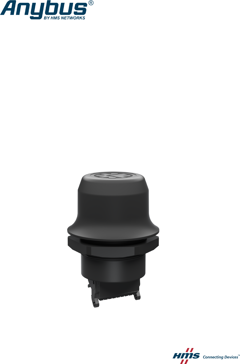
Anybus® Wireless Bolt™ USER MANUAL SCM-1202-007 2.
Important User Information Liability Every care has been taken in the preparation of this document. Please inform HMS Industrial Networks AB of any inaccuracies or omissions. The data and illustrations found in this document are not binding. We, HMS Industrial Networks AB, reserve the right to modify our products in line with our policy of continuous product development.
Table of Contents 1 2 3 4 A Page Preface ................................................................................................................................. 3 1.1 About This Document .......................................................................................................3 1.2 Document History ............................................................................................................3 1.3 Document Conventions ...........................................
This page intentionally left blank
Preface 3 (40) 1 Preface 1.1 About This Document This manual describes how to install and configure Anybus Wireless Bolt. For additional documentation and software downloads, FAQs, troubleshooting guides and technical support, please visit www.anybus.com/support. 1.2 Document History Version Date Description 1.0 1.1 2016-09-15 2016-11-23 First release Minor additions and updates 1.2 2017-12-14 Added configuration example 2.0 2017-04-19 Updated for SP1 2.
Preface 1.3 4 (40) Document Conventions Ordered lists are used for instructions that must be carried out in sequence: 1. First do this 2. Then do this Unordered (bulleted) lists are used for: • Itemized information • Instructions that can be carried out in any order ...and for action-result type instructions: ► This action... → leads to this result Bold typeface indicates interactive parts such as connectors and switches on the hardware, or menus and buttons in a graphical user interface.
Description 5 (40) 2 Description 2.1 Product Description Anybus Wireless Bolt provides wireless communication over WLAN and/or Bluetooth® to wired networks.
Description 2.3 6 (40) Model Name – Certification Identifier The model name consists of a model prefix followed by two designators for interface configuration and functionality. Prefix AWB2 Anybus Wireless Bolt Interface configuration A B Interface 18-pin socket Interface RJ45 and 3-pin power socket Functionality A B C Ethernet Ethernet and RS232/485 Ethernet and CAN Example: AWB2AA = Anybus Wireless Bolt with18-pin plug connector and Ethernet networking only.
Installation 7 (40) 3 Installation 3.1 Safety Caution This equipment emits RF energy in the ISM (Industrial, Scientific, Medical) band. Make sure that all medical devices used in proximity to this device meet appropriate susceptibility specifications for this type of RF energy. This product is recommended for use in both industrial and domestic environments. For industrial environments it is mandatory to use the functional earth connection to comply with immunity requirements.
Installation 3.3 8 (40) Mechanical Installation The device is intended to be mounted on top of a machine or cabinet through an M50 (50.5 mm) hole using the included sealing ring and nut. The top mounting surface (in contact with the sealing) must be flat with a finish equivalent to Ra 3.2 or finer and cleaned and free from oils and greases. Tightening torque: 5 Nm ±10 %. Make sure that the sealing ring is correctly placed in the circular groove in the top part of the housing before tightening the nut.
Installation 3.4 9 (40) Connector The 18-pin connector is common for all models of the Anybus Wireless Bolt. Some pins may have a different function depending on model. Unused pins should not be connected. Fig. 2 Connector The location of the RESET button can be used as a reference for the pin numbering when the connector is attached to the Wireless Bolt. Pin 1 will be the pin closest to the button.
Installation 3.5 10 (40) Ethernet Cabling To make an Ethernet connector cable for Anybus Wireless Bolt: Fig. 3 1. Cut off one of the connectors on a standard Cat5e or Cat6 Ethernet cable. 2. Strip off about 40 mm (1½ inch) of the cable jacket and untwist the orange, orange/white, green and green/white wires. The other wires will not be used. 3. Strip off about 7 mm (¼ inch) of the isolation on each wire. 4.
Installation 3.7 11 (40) RESET Button Fig. 4 RESET button The RESET button is located on the bottom of the unit. When the unit is powered on, press and hold RESET for >10 seconds and then release it to reset to the factory default settings. Recovery Mode If the web interface cannot be accessed, the unit can be reset by starting in Recovery Mode and reinstalling the firmware using Anybus Firmware Manager II, which can be downloaded from www.anybus.com/support.
Configuration 12 (40) 4 Configuration 4.1 General Anybus Wireless Bolt should normally be configured via the web interface. Parameters can be set individually or using one of the pre-configured Easy Config modes. The web interface is accessed by pointing a web browser to the IP address of the Wireless Bolt. The default address is 192.168.0.99. The computer accessing the web interface must be in the same IP subnet as the Wireless Bolt. Fig.
Configuration 13 (40) 4.2 Web Interface 4.2.1 System Overview Fig. 6 System Overview page The System Overview page shows the current settings and connection status for the wired and wireless interfaces. The different parameters are explained in the descriptions of each settings page in this manual. The Help page describes AT commands that can be used for advanced configuration. Save and Reboot This button will be enabled if the unit must be restarted to apply a change.
Configuration 4.2.2 14 (40) Easy Config Fig. 7 Easy Config page To activate an Easy Config mode, select it from the dropdown menu and click on Set. The mode will be activated immediately. Easy Config Modes EC Role Description 1 Bluetooth PANU Configure as Bluetooth client and scan for another client (PANU–PANU). 2 – Reset configuration to factory defaults. 3 – Reset IP settings to factory defaults. 4 5 6 Client WLAN AP Bluetooth NAP Wait for automatic configuration.
Configuration 15 (40) Notes: • Mode 1 will scan for units in mode 4. When a unit in mode 4 is detected, the scanning unit will configure itself as a Bluetooth PANU client, send a connection configuration to the detected unit, and restart. The detected unit will also restart and attempt to connect to the first unit as a PANU client. • Modes 5, 6, 7 and 8 will scan for units in mode 4. The detected units will be reconfigured as clients and the scanning unit will restart as an access point.
Configuration 4.2.3 16 (40) Network Settings Fig. 8 Network Settings page IP Assignment Select static or dynamic IP addressing (DHCP) IP Address Static IP address for the unit The browser should automatically be redirected to the new address after clicking on Save and Reboot (not supported by all browsers).
Configuration 4.2.4 17 (40) WLAN Settings - Client Fig. 9 WLAN Settings - Client Enable Enable/disable the WLAN interface. Operating Mode Choose operation as WLAN Client or Access Point. If Access Point is selected, additional settings will be available. Channel Bands Choose to scan only the 2.4 GHz or 5 GHz channel band, or both (default). The unit can be configured to scan on both the 2.4 GHz and 5 GHz channel bands but can only communicate on one band at a time.
Configuration 18 (40) Advanced Settings Bridge Mode Layer 2 tunnel = All layer 2 data will be bridged over WLAN. Use when multiple devices on both sides of an Ethernet network bridge must be able to communicate via WLAN (many-to-many). Only works between Anybus Wireless Bolt or Wireless Bridge II devices. Layer 2 cloned MAC only = Layer 2 data from only a single MAC address (specified below) will be bridged over WLAN (many-to-one).
Configuration 19 (40) WLAN Channels and World Mode (Client Mode only) Which channels are available for WLAN communication is restricted by the regulatory domain where the unit is operating. Anybus Wireless Bolt supports regulatory domain detection according to the IEEE 802.11d specification. The unit is initially set in World Mode which enables only the universally allowed channels in the 2.4 GHz and 5 GHz bands (see the table below).
Configuration 4.2.5 20 (40) WLAN Settings - Access Point Fig. 10 WLAN Settings - Access Point The following settings are specific for Access Point mode: Network (SSID) Enter an SSID (network name) for the Wireless Bolt. If this entry is left blank, the unit will generate an SSID which includes the last 6 characters of the MAC ID. Authentication Mode Select the authentication/encryption mode to use for the access point.
Configuration 4.2.6 21 (40) Bluetooth Settings – General Fig. 11 Bluetooth Settings Enable Enable/disable the Bluetooth interface. Operating Mode PANU (Client) = The unit will operate as a Bluetooth PAN (Personal Area Network) User device. It can connect to another single Bluetooth PANU device or to a Bluetooth Network Access Point. NAP (Access Point) = The unit will operate as a Bluetooth Network Access Point. It can connect to up to 7 Bluetooth PANU devices.
Configuration 4.2.7 22 (40) Bluetooth Settings – PANU Mode Fig. 12 Bluetooth Settings – PANU PANU mode only Scan for Devices Scans the network for discoverable Bluetooth devices. To connect to a device, select it from the dropdown menu when the scan has completed. Connect To Used when connecting manually to a NAP or PANU device. Connection Scheme Choose whether to select a Bluetooth device by MAC address (default) or Name when connecting manually.
Configuration 4.2.8 23 (40) Bluetooth Settings – NAP Mode Fig. 13 Bluetooth settings – NAP NAP mode only Bridge Mode Standard = Default mode. Layer 3 IP forward = IP data will be bridged over Bluetooth. This mode must be used when connecting to an Android device over Bluetooth. The network must have an active DHCP server. List Nearby Devices Anybus® Wireless Bolt™ User Manual Scans the network and lists discoverable Bluetooth devices. Pairing cannot be initiated in NAP mode. SCM-1202-007 2.
Configuration 4.2.9 24 (40) Bluetooth LE Settings Fig. 14 Bluetooth LE settings Bluetooth LE Settings Operating Mode Disabled = Bluetooth LE disabled (default) Central = Bluetooth LE enabled Please refer to the AT Commands Reference Guide or select Help in the main menu for more information about using Bluetooth LE. Bluetooth must be enabled on the Bluetooth Settings page to use Bluetooth LE. Anybus® Wireless Bolt™ User Manual SCM-1202-007 2.
Configuration 4.2.10 25 (40) Firmware Update To update the firmware in the unit, click on Browse to select a downloaded firmware file, then click on Send to send it to the unit. Fig. 15 Firmware update in progress Both progress bars will turn green when the firmware update has been completed. The unit will then reboot automatically. Fig. 16 Firmware update completed Updating the firmware will not change the configuration settings. Anybus® Wireless Bolt™ User Manual SCM-1202-007 2.
Configuration 4.2.11 26 (40) AT Commands Fig. 17 AT Commands AT commands can be used for setting advanced parameters that are not accessible in the web interface, to read out parameters in text format, and for batch configuration using command scripts. Enter or paste the commands into the text box, then click on Send. The result codes will be displayed below the text box. Click on Help for a complete list of supported AT commands. Anybus® Wireless Bolt™ User Manual SCM-1202-007 2.
Configuration 4.2.12 27 (40) System Settings Fig. 18 System Settings Device Info Device Name Enter a descriptive name for the unit. Password Enter a password for accessing the web interface. Reboot System Reboots the system without applying changes. Cancel All Changes Restores all parameters in the web interface to the currently active values. Factory Reset Resets the unit to the factory default settings and reboots. Setting a secure password for the unit is strongly recommended.
Configuration 4.3 28 (40) Factory Restore Any one of these actions will restore the factory default settings: • Clicking on Factory Restore on the System Settings page • Executing Easy Config Mode 2 • Issuing the AT command AT&F and then restarting the unit • Holding RESET pressed for >10 seconds and then releasing it • Applying voltage to the digital input for >10 seconds Default Network Settings IP Assignment IP Address Subnet Mask Default Gateway Internal DHCP Server Static 192.168.0.
Appendix A: Configuration Examples A Configuration Examples A.1 Ethernet Bridge via WLAN or Bluetooth® 29 (40) Configuration with Easy Config Fig. 19 Ethernet bridge This example describes how to connect two Ethernet network segments via WLAN or Bluetooth using Easy Config. 1. In the web interface of unit 1, activate Easy Config Mode 4. This unit will now be discoverable and open for automatic configuration. Fig. 20 2.
Appendix A: Configuration Examples A.2 30 (40) PROFINET networking via Bluetooth® Configuration with Easy Config Fig. 22 PROFINET wireless network This example describes how to connect a PROFINET IO device and a PROFINET PLC over Bluetooth using two Wireless Bolts and Easy Config. The Wireless Bolts will be configured with PROFINET optimization, which means that PROFINET messages will have priority over TCP/IP frames.
Appendix A: Configuration Examples A.3 31 (40) EtherNet/IP™ Networking via Bluetooth® Configuration with Easy Config Fig. 23 EtherNet/IP wireless network This example describes how to connect an EtherNet/IP IO device and an EtherNet/IP PLC over Bluetooth using two Wireless Bolts and Easy Config. See the respective documentation for the IO device and PLC on how to configure them for EtherNet/IP communication. Configuration 1. Reset both Wireless Bolts to the factory default settings. 2.
Appendix A: Configuration Examples A.4 32 (40) Ethernet network to existing WLAN Fig. 24 Connecting to a WLAN This example describes how to connect a machine with an internal Ethernet network to an existing WLAN. This setup allows traffic on network layer 3, but not layer 2. This means that TCP/IP based protocols such as EtherNet/IP, Modbus TCP and BACnet can be used on the WLAN, but not protocols that use layer 2 traffic, such as PROFINET. Configuration 1.
Appendix A: Configuration Examples A.5 33 (40) Adding single Ethernet node to WLAN Fig. 25 Adding WLAN connectivity This example shows how to connect a PLC with an Ethernet network interface to an existing WLAN with support for layer 2 and layer 3 traffic. The WLAN interface in the Wireless Bolt will clone the MAC address of the Ethernet interface in the PLC. Only a single Ethernet node will be able to communicate via a third-party WLAN access point in this setup. Configuration 1.
Appendix A: Configuration Examples A.6 34 (40) Accessing PLC via WLAN from Handheld Device Fig. 26 Accessing a PLC from a handheld device using WLAN This example describes how to use a Wireless Bolt to access the web interface of a PLC on a wired network from a tablet or smartphone which uses DHCP. The Wireless Bolt will function as a WLAN access point. Please refer to the documentation for the handheld device and PLC on how to configure their respective network settings. Configuration 1.
Appendix A: Configuration Examples 3. 35 (40) In WLAN Settings, set Operating Mode to Access Point. Fig. 27 WLAN Settings 4. Enter a unique SSID (network name) for the new wireless network. 5. Set Authentication Mode to WPA2 and enter a passkey. 6. Select a Channel band and a Channel. 7. Click on Save and Reboot. You should now be able to connect to the SSID of the Wireless Bolt on your handheld device and access the PLC by by entering its IP address in a browser.
Appendix B: Wireless Technology Basics B 36 (40) Wireless Technology Basics Wireless technology is based on the propagation and reception of electromagnetic waves. These waves respond in different ways in terms of propagation, dispersion, diffraction and reflection depending on their frequency and the medium in which they are travelling. To enable communication there should optimally be an unobstructed line of sight between the antennas of the devices.
Appendix C: Technical Data 37 (40) C Technical Data C.1 Hardware Specifications Order code AWB2000 AWB2001 Color Black White top and black base Wired interface type Ethernet Connector Included plug connector Antenna Internal dual-band 2.
Appendix C: Technical Data C.2 38 (40) Communication Ethernet Ethernet interface 10/100BASE-T with automatic MDI/MDIX auto cross-over detection Ethernet protocols IP, TCP, UDP, HTTP, LLDP, ARP, DHCP Client/Server, DNS support PROFINET IO, EtherNet/IP, Modbus-TCP Wireless LAN Wireless standards IEEE 802.11 a, b, g, n, d, r Operation modes Access point or client Fast roaming IEEE 802.11r (client) Max. number of clients for access point 7 WLAN channels 2.4 GHz Access Point: 1–11 2.
This page intentionally left blank
last page © 2019 HMS Industrial Networks Box 4126 300 04 Halmstad, Sweden info@hms.se SCM-1202-007 2.