Anybus® Wireless Bridge II™ USER MANUAL SCM-1202-032 1.
Important User Information Liability Every care has been taken in the preparation of this document. Please inform HMS Industrial Networks AB of any inaccuracies or omissions. The data and illustrations found in this document are not binding. We, HMS Industrial Networks AB, reserve the right to modify our products in line with our policy of continuous product development.
Table of Contents 1 Page Preface ............................................................................................................................... 3 1.1 About This Document.....................................................................................................3 1.2 Document history...........................................................................................................3 1.3 Document Conventions ..............................................................
This page intentionally left blank
Preface 3 (36) 1 Preface 1.1 About This Document This document describes how to install and configure Anybus Wireless Bridge II. For additional related documentation and file downloads, please visit the Anybus support website at www.anybus.com/support. 1.2 Document history Version Date Description 1.0 2017-03-31 First public release 1.1 2017-04-19 Minor update 1.2 2017-07-14 Added Bluetooth bridge mode 1.
Preface 1.3 4 (36) Document Conventions Ordered lists are used for instructions that must be carried out in sequence: 1. First do this 2. Then do this Unordered (bulleted) lists are used for: • Itemized information • Instructions that can be carried out in any order ...and for action-result type instructions: ► This action... ➨ leads to this result Bold typeface indicates interactive parts such as connectors and switches on the hardware, or menus and buttons in a graphical user interface.
Product Description 2 5 (36) Product Description Anybus Wireless Bridge II provides wireless communication over WLAN and/or Bluetooth® to wired networks.
Installation 3 6 (36) Installation Caution This equipment emits RF energy in the ISM (Industrial, Scientific, Medical) band. Make sure that all medical devices used in proximity to this device meet appropriate susceptibility specifications for this type of RF energy. This product is recommended for use in both industrial and domestic environments. For industrial environments it is mandatory to use the functional earth connection to comply with immunity requirements.
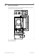
Installation 3.2 7 (36) Mechanical Installation R 112.5 33.2 92.7 26.4 82 12.2 Anybus Wireless Bridge II can be screw-mounted directly onto a flat surface or mounted on a standard DIN rail using the optional DIN mounting kit. 2 19.8 22 30 58 4.9 15.4 67.8 Fig. 1 Installation drawing All measurements are in mm. Anybus® Wireless Bridge II™ User Manual SCM-1202-032 1.
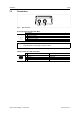
Installation 3.3 8 (36) Connectors Power Fig. 2 LAN M12 connectors Power Connector (A-coded male M12) Pin 1 2 3 4 5 Function Power + (9–30 V) Digital Input Ground Power Ground Digital Input + (9–30 V) Functional Earth Signal wiring for the digital input must be carried in the same cable as power and functional earth if wiring length exceeds 3 meters.
Installation 3.4 9 (36) LED Indicators Fig.
Configuration 10 (36) 4 Configuration 4.1 General Anybus Wireless Bridge II can be configured via the web interface or using one of the pre-configured Easy Config modes. Advanced configuration can be carried out by issuing AT (modem) commands through the web interface or over a Telnet or RAW TCP connection to port 8080. 4.2 Easy Config 1. Power on the unit and wait for the Link Quality LEDs to light up and go out again, then press and release the MODE button. – 2.
Configuration 4.3 11 (36) Web Interface The web interface is accessed by pointing a web browser to the IP address of the Wireless Bridge. The default IP address is 192.168.0.99. The computer accessing the web interface must be in the same IP subnet as the Wireless Bridge. The web interface is designed for the current stable versions of Internet Explorer, Chrome, Firefox and Safari. Other browsers may not support the full functionality of the web interface. 4.3.1 System Overview Fig.
Configuration 4.3.2 12 (36) Easy Config Fig. 5 Easy Config page To activate an Easy Config mode, select it from the dropdown menu and click on Set. Easy Config Modes Mode 2 3 4 5 6 Role — — Client WLAN AP Bluetooth NAP Description Reset configuration to factory defaults Reset IP settings to factory defaults Wait for discovery and configuration Discover units in Mode 4 and configure them as clients LED B A B C A C B C Modes 5 and 6 will scan for units in Mode 4.
Configuration 4.3.3 13 (36) Network Settings Fig. 6 Network Settings page IP Assignment Select static or dynamic IP addressing (DHCP) IP Address Static IP address for the unit Subnet Mask Subnet mask when using static IP Default Gateway Default gateway when using static IP Internal DHCP Server Disabled: No internal DHCP functionality DHCP Relay Enabled: The unit can receive a DHCP request on one interface and resend it to a DHCP server located on one of the other interfaces.
Configuration 4.3.4 14 (36) WLAN Settings – Client Mode Fig. 7 WLAN Settings – Client Enable Enable/disable the WLAN interface. Operating Mode Choose if the unit should operate as a WLAN Client or Access Point. If Access Point is selected, additional parameters will be visible. Channel Bands Choose to scan for networks on either the 2.4 GHz or 5 GHz channel band, or on both (default). The unit must be rebooted to enable the new setting. The unit can be configured to scan on both the 2.
Configuration 15 (36) Fig. 8 WLAN Client – Advanced Settings Advanced Settings Bridge Mode Layer 2 tunnel = All layer 2 data will be bridged over WLAN. This mode should be used when multiple devices on both sides of an Ethernet network bridge must be able to communicate via WLAN (many-to-many). This mode will only work between two Anybus Wireless Bolt or Wireless Bridge II devices.
Configuration 4.3.5 16 (36) WLAN Settings – Access Point Mode Fig. 9 WLAN Settings – Access Point The following settings are specific when Access Point mode is selected. Network (SSID) Enter an SSID (network name) for the Wireless Bridge. If this entry is left blank, the unit will generate an SSID which includes the last 6 characters of the MAC ID. Authentication Mode Select the authentication/encryption mode to use for the access point.
Configuration 4.3.6 17 (36) Bluetooth Settings – General Fig. 10 Bluetooth Settings Enable Enable/disable the Bluetooth interface. Operating Mode PANU (Client) = The unit will operate as a Bluetooth PAN (Personal Area Network) User device. It can connect to another single Bluetooth PANU device or to a Bluetooth Network Access Point. NAP (Access Point) = The unit will operate as a Bluetooth Network Access Point. It can connect to up to 7 Bluetooth PANU devices.
Configuration 4.3.7 18 (36) Bluetooth Settings – PANU Mode Fig. 11 Bluetooth Settings – PANU PANU mode only Scan for Devices Scans the network for discoverable Bluetooth devices. To connect to a device, select it from the dropdown menu when the scan has completed. Connect To Used when connecting manually to a NAP or PANU device. Connection Scheme Choose whether to select a Bluetooth device by MAC address or name when connecting manually. Name Name of the Bluetooth device to connect to.
Configuration 4.3.8 19 (36) Bluetooth Settings – NAP Mode Fig. 12 Bluetooth settings – NAP NAP mode only Bridge Mode Standard = Default mode. Layer 3 IP forward = IP data will be bridged over Bluetooth. This mode must be used when connecting to an Android device over Bluetooth. The network must have an active DHCP server. List Nearby Devices Anybus® Wireless Bridge II™ User Manual Scans the network and lists discoverable Bluetooth devices. Pairing cannot be initiated in NAP mode. SCM-1202-032 1.
Configuration 4.3.9 20 (36) Firmware Update Fig. 13 Firmware Update Click on Browse to select a firmware file, then click on Send to download it to the unit. Both progress bars will turn green when the firmware update has been completed. The unit will then reboot automatically. Anybus® Wireless Bridge II™ User Manual SCM-1202-032 1.
Configuration 4.3.10 21 (36) AT Commands Fig. 14 AT Commands AT commands can be used for setting advanced parameters that are not accessible in the web interface, to read out parameters in text format, and for batch configuration using command scripts. Enter or paste the commands into the text box, then click on Send. The result codes will be displayed below the text box. See the AT Commands Reference Guide for a complete list of supported AT commands.
Configuration 4.3.11 22 (36) System Settings Fig. 15 System Settings Device Name Enter a descriptive name for the unit. Password Enter a password for accessing the web interface. Reboot System Reboots the system without applying changes. Cancel All Changes Restores all parameters in the web interface to the currently active values. Factory Reset Resets the unit to the factory default settings and reboots. Setting a secure password for the unit is strongly recommended.
Configuration 4.4 23 (36) Factory Restore The unit can be restored to the factory default settings using any of the following methods: ► Press and hold the MODE button for >10 seconds and then release it ► Execute Easy Config Mode 2 ► Click on Factory Restore on the System Settings page ► Issue the AT command AT&F and reboot Default Network Settings IP Assignment IP Address Subnet Mask Default Gateway Static 192.168.0.99 255.255.255.0 192.168.0.
Configuration 4.5 24 (36) MODE Button Fig. 16 Overlay The MODE button can be used to restart or reset the unit as well as for selecting an Easy Config mode. ► Press and hold the button for >10 seconds and then release it to reset to the factory default settings (when the unit is powered on). ► Press and hold the button during startup to enter Recovery Mode.
Appendix A: Configuration Examples A 25 (36) Configuration Examples The following examples require that you have installed the Anybus Wireless Bridge II and that you understand how to access and use the web interface. A.1 • All the examples start out from the factory default settings. • Settings not mentioned in the examples should be left at their default values.
Appendix A: Configuration Examples A.2 26 (36) PROFINET networking via Bluetooth (Easy Config) Fig. 18 PROFINET wireless network This example describes how to connect a PROFINET IO device and a PROFINET PLC via Bluetooth using two Wireless Bridges and Easy Config. The Easy Config modes can be selected using only the MODE button or through the web interface. Configuration Please refer to the documentation for the IO device and the PLC regarding how to configure PROFINET communication. 1.
Appendix A: Configuration Examples A.3 27 (36) EtherNet/IP networking via Bluetooth (Easy Config) Fig. 19 EtherNet/IP wireless network This example describes how to connect an EtherNet/IP IO device and an EtherNet/IP PLC via Bluetooth using two Wireless Bridges and Easy Config. The Easy Config modes can be selected using only the MODE button or through the web interface. Configuration Please refer to the documentation for the IO device and PLC regarding how to configure EtherNet/IP communication. 1.
Appendix A: Configuration Examples A.4 28 (36) Connecting an Ethernet network to an existing WLAN Fig. 20 Connecting to a WLAN This example describes how to connect a machine with an internal Ethernet network to an existing WLAN. This setup allows traffic on network layer 3, but not layer 2. This means that TCP/IP based protocols such as EtherNet/IP, Modbus TCP and BACnet can be used on the WLAN, but not protocols that use layer 2 traffic, such as PROFINET. Configuration 1.
Appendix A: Configuration Examples A.5 29 (36) Adding wireless connectivity to a single Ethernet node Fig. 21 Adding WLAN connectivity This example shows how to connect a PLC to an existing WLAN with support for layer 2 and layer 3 traffic. The WLAN interface in the Wireless Bridge will clone the MAC address of the Ethernet interface in the PLC. Only a single Ethernet node can communicate via a third-party WLAN access point in this setup. Configuration 1.
Appendix A: Configuration Examples A.6 30 (36) Accessing a PLC from a handheld device over WLAN Fig. 22 Accessing a PLC from a handheld device using WLAN This example describes how to use a Wireless Bridge to allow access to the web interface of a PLC or other device on a wired network from a tablet or smartphone that uses dynamic IP addressing (DHCP). The Wireless Bridge will operate as a WLAN access point.
Appendix B: Wireless Technology Basics B 31 (36) Wireless Technology Basics Wireless technology is based on the propagation and reception of electromagnetic waves. These waves respond in different ways in terms of propagation, dispersion, diffraction and reflection depending on their frequency and the medium in which they are travelling. To enable communication there should optimally be an unobstructed line of sight between the antennas of the devices.
Appendix C: Technical Data C Technical Data C.
Appendix C: Technical Data C.2 33 (36) Internal Antenna Characteristics Anybus Wireless Bridge II has 3 independent quarter wave monopole antennas. The following radiation diagrams and tables show the characteristics of the different antennas as measured under laboratory test conditions. The diagrams can be used as a general guide for finding the optimal placement and orientation of the units. The diagrams use a color spectrum from violet to red to indicate signal gain.
Appendix C: Technical Data 34 (36) 2.4 GHz MIMO Antenna Fig. 26 2.4 GHz MIMO antenna gain and directivity in horizontal and vertical planes Test Antenna Section F Avg Gain Peak Gain Dir Comment # 168 169 170 MIMO - MHz dBi % dBi dB In Plastic Box 2400 2440 2485 -1.95 63.8 -1.65 68.4 -1.42 72.1 +2.66 +2.88 +2.76 4.6 4.5 4.2 Anybus® Wireless Bridge II™ User Manual SCM-1202-032 1.
This page intentionally left blank
last page © 2017 HMS Industrial Networks AB Box 4126 300 04 Halmstad, Sweden info@hms.se SCM-1202-032 1.3.