GT400 Operators Manual Ft. Atkinson, Wisconsin USA Panningen, The Netherlands www.digi-star.
GT400 User’s Manual D3831 Rev B
TABLE OF CONTENTS Table of Contents TECHNICAL SPECIFICATIONS ..................................................................... 1 SAFETY DURING USE ................................................................................... 2 Cleaning ....................................................................................................... 2 Charging Battery and Welding ..................................................................... 2 INDICATOR OVERVIEW ......................................
Table of Contents All rights reserved. Reproduction of any part of this manual in any form whatsoever without Digi-Star’s express written permission is forbidden. The contents of this manual are subject to change without notice. All efforts have been made to assure the accuracy of the contents of this manual. However, should any errors be detected, Digi-Star would greatly appreciate being informed of them.
TECHNICAL SPECIFICATIONS Technical Specifications SIZE 7.33” long x 5.25” high x 3.38” wide (186mm x 133mm x 85mm) DISPLAY RESOLUTION .01, .02, .05, .1, .2, .5, 1, 2, 5, 10, 20, 50, 100 WEIGHT 2 lbs (.91 Kg) DISPLAY UPDATE RATE Selectable: 1, 2, 3, 4 times/sec. HELP MESSAGES Context sensitive help messages in 10 languages Long messages are scrolled MAX. DISPLAY RESOLUTION Adjustable to 40,000 counts max. TRANSDUCER EXCITATION 8 volts D.C.
SAFETY DURING USE Safety During Use Caution Cleaning Do not use running water (high pressure cleaners, hoses) to clean the indicator. Charging Battery and Welding Disconnect all cables from the weighing indicator before charging the battery or welding on the machine. If cables are left connected, the weighing indicator and connected load cells could be damaged.
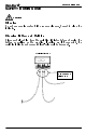
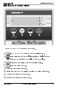
Indicator Overview INDICATOR OVERVIEW 5 6 7 8 1 2 3 4 Note: See page 17 for installation instructions. 1 - ZERO/BALANCE operation when the scale is empty. 2 - start unloading and stop unloading, indicator displays amount unloaded, stores or prints data to serial port when complete. 3 - edit name and display weight accumulation value. 4 - turns the unit on and off. 5 Net – arrow flashes in net mode. 6 Print – arrow flashes when printing or saving to Data-Down-Loader.
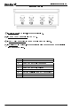
Bottom Panel 9 9 10 11 Indicator Overview 12 - Remote Port – Optional, for remote display. 10 - Power Cord Connection – +12 VDC. 11 - Load Cell Connection – Connect cable from the J-Box. 12 - Serial/J905 – Optional, to communicate with computer and other digital Input/Output devices.
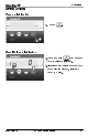
Operation OPERATION Turn on Indicator 1. Press . 1 Zero Balance Indicator 1. Press and hold 1 0 2 for 3 seconds to zero balance indicator. 2. Flashing arrow points to gross next to the display window, indicator ready to weigh.
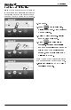
Operation Loading and Unloading For best accuracy park scale on level surface and allow weight reading to stabilize before Zero balancing the scale and before beginning to unload. Note: 1. Load cart. 2. Press to begin unloading. Display reads Zero. Arrows point to Net and Unload. 3. Unload weight from cart. Display shows amount unloaded. 2 4 4 5 6 4. Press . after unloading is complete.
Operation Field ID 6 character identification value stored in internal memory of indicator to identify field being unloaded, truck being loaded or other information. 3 2 1 4 1. Press . FIELD is displayed and a flashing cursor or character is displayed in the first position. 2. Press to scroll available characters. Hold for 4 seconds to increase second scroll rate. 3. Press to scroll backwards through available characters. Press to move to the next character. 4. Press to accept and save.
Operation Print Formats Three print formats are available to output PRTACC value and FIELD ID to DDL or printer. PRTAC1: FIELD ID, 4856, GR, 274575, PA, 05FE08, I:44P PRTAC2: FIELD ID, 05FE08, I:44P 4856, GR, 274575, PA Includes following information: • Field ID • Weight • Weight Tag (NE, GR, Load/Unload) • Accumulated Weight • Print Accumulator Tag • Date and Time PRTAC3: FIELD3, 5977, LB, ,GR, 3097I9,PA,05FE08, 4:42P Includes above and adds “Unit of Measure”.
Operation Saving/Printing Gross Weights (Optional w/ Serial Option) 1. Press and hold three seconds to send weight to serial port. Each time this command is executed the value displayed is added to the “PRTACC” which is the accumulated weight. Weight is accumulated until cleared. 1 Turning Off the Indicator 1. Press until “BYE” is displayed.
Weighing Errors WEIGHING ERRORS Over-Capacity Limit (OVRCAP) The display shows the message "OVRCAP" if the weight on the scale system exceeds the capacity limit. The capacity value is entered in SETUP to warn of overloading the scale system. Over Range (+RANGE) The display shows the message "+RANGE" if the weight on the scale system exceeds the maximum weight measurable by the scale system. The over range value is always the system’s maximum A/D counts multiplied by the scaling factor.
MENUS AND CALIBRATION Menus and Calibration The Indicator has optional settings that allow flexibility in the way that the scale is used and data is collected. Changing Options Using Long Form Setup Enter Long Form Setup by holding and for three seconds. Press to advance to desired menu 1,2,3,4,CALIB, or EXIT, press to select. Press to advance to desired setting. Press to advance setting to desired option. Press to save setting option and advance to next setting.
Menus and Calibration SETTING [display] OPTIONS [displayed] BOLD=DEFAULT DESCRIPTION MENU 2. CLOCK, PRINTER, COMMUNICATIONS & ESTIMATED WEIGHT FEATURES TIME FORMAT 24 HR (time f) AM/PM (time) XX:XX:XX DATE FORMAT 1-mm-dd 2-mm/dd/yy 3-mm/dd/yyyy 4-dd-mm 5-dd/mm/yy 6-dd/mm/yyyy 7-ddmoyy 8-ddmoyyyy.
Menus and Calibration SETTING [display] PRINT FORMAT OPTIONS [displayed] BOLD=DEFAULT AUTO WTRCTM (prtfmt) WTONLY EIDINF DOWNLD EID DT+TM EIDVID ID+TM PRTAC1 IDWTTM PRTAC2 ANIMAL PRTAC3 3200-A FEED-1 3200-B PRTAC4 32-TMR PRTAC5 DATCHI PRTAC6 FDINFO BUFINF (zerout) (CI DLY) C2 DLY) ( (prtacc) COUNT) DISPLAY UNIT (lb-kg) CAPACITY (cap) Select alternate & comma (CSV) formats. Perform the Zero/Balance for SCOREM #11 weight output and Analog Output Option (4-20mA).
SHORT FORM CALIBRATION Short Form Calibration The Short Form Setup & Calibration procedure allows you to change “SETUP” and “CAL” numbers of indicator. Do not attempt to calibrate scale if indicator is not reading stable weights. Calibration procedure will not fix instability, inconsistencies, or flashing "RANGE" messages. Obtain Current Set-up and Calibration Number Write down current SETUP and CAL numbers of your GT 400 indicator. These numbers are displayed during Self Test.
Short Form Calibration CALIBRATION NUMBER The “CAL” number is adjusted to make scale read proper weight for different load cells and to make accuracy adjustments on a scale system. Systems should be checked with known weights and adjusted if necessary to insure accuracy. Both setup and calibration numbers are changed to convert a scale from lbs to kgs. Calibrating Scale For Maximum Accuracy To accurately calibrate scale, you need a large amount of weight that has a known value.
Short Form Calibration Enter A New Setup And Calibration Number 1 4 3 1 1. Press and hold and for 3 seconds to enter short form calibration. 2. The display will flash “SETUP” and then display the 6-digit setup number with the right digit flashing. 3. Press several times to increment digit to it proper value. 4. Press to advance digit left. Repeat steps 3 and 4 for each digit as required. 6 5 5. Press to enter new setup number and display calibration number.
Installation INSTALLATION Indicator Mounting RAIL MOUNT KEY A B C D E F G WING MOUNT WEDGE MOUNT STANDARD PART NUMBER DESCRIPTION 403769 BRACKET – STR TOP MOUNT 403980 BRACKET – ROBO MOUNTING 403770 BRACKET – WING MOUNT 405069 U-BOLT, 1/4-20 X 3.
Installation Cable Connection Scale Indicator Power Cord Remote Indicator (Optional) Pin To 12VDC Power Supply 1 Red +Terminal 2 Black -Terminal 3 Orange Alarm Out 4 Blue Remote Input See Connect Load Cells to J-Box (page 19) Indicator Connection Diagram J-Box Connection Remote Port (Optional) Power Cord Connection Serial/J905 (Optional) Bottom Panel Cable Connections 18 GT400 User’s Manual D3831 Rev B
Installation Connect Load Cells to J-Box Connect load cell wires to terminal blocks. See Wire Color Key J-Box Illustrated for 4 Load Cell Installation Wire Color Key Color Description 1 White Signal + 2 Green Signal - 3 Red Excitation + 4 Black Excitation - 5 Shield Shield Tighten Nuts J-Box Cable Load Cell Cable Connect to Indicator bottom Panel. J-Box Connections Load Cell Direction Observe direction of arrow when installing load cell.
Optional Equipment OPTIONAL EQUIPMENT Data Transfer Options Kit Data Down Loader Allows transfer of data from indicator to PC. (Optional serial/J905 port must already be installed in indicator) Remote Indicators RD440 small remote display RD2400V backlit remote display with 1.
Troubleshooting TROUBLESHOOTING FLOW CHART START YES Is the reading on the Indicator stable? Does the indicator come on? If your display is unstable, or flashes “±RANGE” disconnect the j-box cord from Indicator. Is display still unstable? NO YES Put your weight on each NO load cell. Does the indicator respond to your weight? Check all J-Box and Load Cell YES cables for cuts or pinched/flat spots. Are the readings all positive? If not Load Cell is upside down. Does the scale weigh you approx.
FLOW CHART Continued 1. Disconnect all the Load Cell wires from the terminal blocks inside the J-Box (leave the Indicator on while connecting and disconnecting the wires, it will not damage Load Cells or Indicator if wires are shorted during this step). Is reading on Indicator stable? YES Hook up the Load Cells to the J-Box one at a time (only one Load Cell connected at a time). This will get a reading for each Load Cell.