Safety instruction Always follow the safety instructions during assembly and usage, to avoid any unnecessary damage to the machine or individual injury Please contact our customer service first if you have any issue after receiving the products. Be cautious when using the scraper. Never direct the scraper towards your hand. In case of emergency, please immediately cut off the power of Anaerobic 3D printer and contact the technical support. exclusive 3D printer includes moving parts that can cause injury.
Contents Technical Specification 1 Packing list 2 Product Overview eee 3 Menu Directory mere eee 4 Installation.
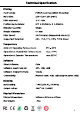
Technical Specification Printing Technology: Build Size: Print accuracy: Positioning Accuracy: Extrude Quantity: Nozzle Diameter: Print Speed: Supported Materials: FDM (Fused Deposition Modeling) 220% 220% 250 (mm3) +0.1 mm X/Y 0.0125mm, Z 0.002mm Single 0.
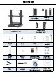
Packing list Control Box Filament holder } ¥ Mega Zero 2.0 Data cable & Power cord ’ dry M4*20 M5% Tout . PCs PCS PCS Tool kit ba M5*45 Washer Memory card Assembly PCS PCs & Card reader instruction => | mma .
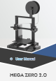
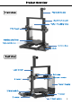
Product Overview Front view Filament holder Aluminum beam = Teflon Feeding tube Print head —S = i Printing platform — Adjustable nut Control box Back view Lead screw Extrude ruder motor X motor Power Supply Z limit switch —— gum 68 Y motor Z motor — ¥ limit switch 3
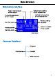
Menu Directory information interface Target temperature of the nozzle Current temperature of the nozzle Machine name Printing speed Machine state Common Functions Main menu —— Target temperature of the heated bed Current temperature of the heated bed Model cooling fan state Current location of the nozzle ag sno Print time i Prepare ree Control t—— Print from SD
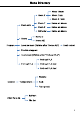
Menu Directory Move 10mm Move X Move Tmm Move 0.1mm .
Menu Directory Common functions in printing Tune + Speed: + Nozzle: + Bed: —+ Fan speed: Flow: Nozzle: Main menu Control —» Temperature Bed: Fan speed: Pause print Stop print
Installation 1. Be cautious during assembly as some parts may have sharp edges. 2. Iris suggested to use a flat desktop and place the parts in an orderly manner for quick assembly. 3. The color of some parts may be different from what in the manual, but the assembly is the same. 4, Firmware has been per-uploaded to the motherboard. After completing the assembly, please level the platform and load the filament then you could start the first test print.
Installation 1. Install frame Washer —ssl Sy ! ME*45 i 2. Install power box Ma*20 | Locking the holes on right side K-wands aluminum beam Note: if the holes on aluminum beam are blocked, move the X-axis aluminum up and down to expose them.
Installation 5. Wiring: connect all these wires to their corresponding ports by the label respectively. Z limit switch NTC wires {random color) heated bed wires The power cords should Y limit switch ¥Y motor be connected under the (random color) aluminum beams without twisting or arching.
Installation 6. Install the magnetic sticker Attach the magnetic sticker to the platform.
Leveling it is essential to level the print platform of a 3D printer. Once leveled, it is not necessary to level every time before each printing. Please follow the procedures below: 1. Manual leveling (1) Select correct voltage mode of the power box according to your local voltage ratings (110V/220V) before plug in. The default setting is 220V. In some cases, 220V labeled as "230%, 170V labeled as "115" (2) Power on the machine.
Leveling (3) After home, press the knob on the screen to enter the main menu, navigate and press the knob : “Prepare”— " Level corners”, and the print head will move to the first leveling point. Ln Move axis {tame Bla > ae Bis aa (4) Put a piece of A4 paper at the first leveling point on the printing platform. Then manually adjust (tighten or loosen) the corresponding nut underneath the printing platform.
Leveling (5) After the leveling of the first point, Press the knob to choose “Next corner” forth leveling of the next point (refer to the step (4) ). The leveling of the four points in the figure below must be completed. a Lee ee After the leveling of the fourth point, you must choose "Next corner” to return to the first point to level again. Please adjust the 4 points of the platform 2 or 3 times to ensure leveling result is OK, otherwise the platform and nozzle could be worn.
Leveling 2. Supplements to leveling Case @: After homing, the nozzle is still much lower than the platform, even if the 4 nuts underneath are fully tightened. Case @: After homing, the nozzle is still too far from the platform, even if the 4 nuts underneath are fully loosened. How to solve this: Case @: adjust Z limit switch up. Case @: adjust Z limit switch down. After adjusting, please home and level again.
Print model 1. Load the filament (1) Return to the main menu, then navigate and press the knob : “Prepare” — “ Move axis” — “Move Z" — “Move 10mm” , turn the knob to set the Z value to 100, and then press the knob to confirm it. The print head will rise 100mm. Control Ham cd SE Level comers Move 2 Baal ie Bali Move & Move axis Mace 10mm Sn ia (2) Return to the “Prepare” menu, navigate and press the knob to choose “Preheat PLA” — “Preheat PLA End”.
Print model Insert the filament into the extrude till here. (4) Enter the main menu, navigate and press the knob : “Prepare” — “Move axis” — “Extrude” — “Move 10mm". Turn the knob until the filament is extruded at the nozzle. Then press the knob to return and clean the filament residue on the nozzle tip.
Print model Note: During feeding, if the melted filament is not smooth or too thin, please adjust the extrusion force by rotating the knob as shown below. If the melted filament is not smooth, please increase the extrusion force by rotating clockwise. 2. Print the model If the melted filament is too thin, please reduce the extrusion force by rotating counterclockwise. Mote: The better distance for extruding filament is about 18 mm.You may adjust the distance of the screw for the different filament.
Print model ahi 5 nn . ETE There might be 3 kinds of results for the first layer of the test prints. A: Nozzle too low, lack of extrusion, the nozzle rub against the platform. Slowly tighten the corresponding nuts underneath by half circle or level again. Nozzle too low Filament B: Proper nozzle height, good extrusion and adhesion.
Print model C: Nozzle too high, large gap, filaments do not even adhere to the platform. Slowly loosen the corresponding nuts underneath the platform by half circle or level again. Nozzle too high Filament i If you can't improve the model printing effect by fine-tuning the adjustable nuts, please level again. Nozzle and platform are still in high temperature when printing is finished, Please be cautious to avoid injury.Wait for them to cool before removing the magnetic sticker.
Print model After several times of leveling, if the printing effect is still poor, it may be that the D-shape wheels do not run smoothly or idle during printing. The D-shape wheels has been adjusted in factory, but they may be loose due to transportation. Check the D-shape wheels: Pull the X module up and down. If the Shape wheels along Z axis do not roll smoothly or idle, use a wrench to slowly turn the hexagonal pillars until the D-shape wheels roll smoothly.
Driver installation There are two operational modes for Mega Zero 2.0 : print offline and print online. Print offline: As shown previously, insert memory card to right side of the control box, press the knob to select “Print from SD” and print a selected file (G Code files ONLY). Print online: Install CH340 driver to bridge PC and machine, and install Cara for slicing and control the machine to print via data cable.
Introduction to slicing software Introduction of slicing software: @Cara installation, @Machine settings, ®Import the configuration file , @ Manipulate 3D model in Cara, ®Slice and preview, ®Print online, @Print offline 1. Cara installation 3D printer reads Geode file and prints. It is necessary to convert 3D files (such as stl file) into Geode files for machine to recognize. Software that convert 3D files into Geode files is called slicing software.
Introduction to slicing software According to the wizard, we have selected the "Any cubic i3 Mega" model. Now, we will set the model parameters of Mega Zero 2.0 based on that model. (1) Click “Manage printers”, as shown below. yi Be Ape sg © El seen £5 Dimmer Cue fly (2) Click "rename" to change the machine name to "Any cubic Mega Zero 2.0", and then click "Machine Settings" .
Introduction to slicing software 3. Import the configuration file After continuous testing, we provided users the suggested printing parameters of different filaments for Mega Zero 2.0, and the user could directly import the parameter files in the memory card to the software. (1) Click “Settings” "Configure setting visibility...", and then check "Check all" to make all settings visible.
Introduction to slicing software £3 Cure 7 x © Housemaid ly deported profile Sustained paternosters MEGA-TRAD 2 OPI (3) Select the configuration file that you just imported. Click to open “Print settings” BF Layer Height anon a Supp a Adhesion ck to open the print parameters interface Norma Dem Som Dion omen { Monte Profiles .
Introduction to slicing software 4. Manipulate 3D model in Cara In the Cara software interface, click on the “File” — “Open to import your own three-dimensional format model (such as stl file). Users can “Rotate” “Scale” “Mirror” the model. As shown below: Sims Other operations: a) Position change: left click on the model, hold on and drag the model to move. b) Zoom in/out: scroll the mouse wheel. ¢) Change viewing angle: right click and move the mouse.
Introduction to slicing software Note: as shown in the figure on the right, the gray color of the model indicates that the model is out of print range. After importing the model, users can customize the printing parameters according to individual needs. But the configuration files that we provide are suggested. Note: "Suggested parameters MEGA-ZERO profiterole” file is prepared for PLA filament, and "Suggested parameters MEGA-ZERO profiterole” file is prepared for TPU filament.
Introduction to slicing software 5. Slice and preview After setting the printing parameters, click the "Slice" button in the lower right corner of the software. After the slicing is finished, click the "preview" button to preview the simulated printing effect in the preview view. (0) Hours Minutes & Fawn nae Click to preview the simulated printing effect. =» FH preview view. : | . ane (5) Bones 28 minutes a Lain 6. Print online After the parameters have been set up, you can print online via Cara.
Introduction to slicing software After connecting the data line, Cara will automatically connect to the printer. After waiting for more than ten seconds, the operation panel will be displayed on the right side of the interface. User can control printer through the operation panel. {in the process of printing, do not plug the data line, or it will interrupt the printing) £3 mime Cus.
Introduction to slicing software 7. Print offline After slicing, click "save to file" in the lower right corner of Cara software. Save the model G Code file to the memory card, and then insert the memory card to the printer and control via the touch screen for offline printing. Note: The file name should only contain English letters, underscore and space. File name contains special characters could not be recognized by the printer.
Resume from outage During printing, if there is an accident power loss, the print will stop immediately. But after power comes back, customers could “Resume print” , machine will home first and continue on the unfinished object. Sa Ele Sn Note: @ “Resume from outage” is valid only for offline printing. @ In slicing software (i.e. Curare, it is required to place the model at the rear of the platform.
Maintenance It is necessary to perform routine maintenance to the 3D printer to achieve consistent and quality results. Some maintenance suggestions are shown as below: 1. Clean the nozzle with a needle under preheating conditions. If the filament residue in the nozzle could not be cleared 100%, please replace the nozzle. 2. Regularly add lubricating oil to smooth rods, linear bearings, lead screws, brass nuts, etc. It can minimize the wear-out failure of those moving parts. 3.
Troubleshooting 1. Motor shaking or abnormal sound © @ ® The corresponding limit switch could not be triggered when home. Check the wiring, and inspect all obstacles by manually moving the corresponding axis. The motor cable are not connected properly, check each connection and then inspect the cable routing for any fault. The motor is damaged. 2. File not printing or memory card failure Remove the memory card and insert into PC. Open the G Code files using text editor (eg.
Troubleshooting 4. No extrusion or extrusion motor knocking Filament tangles on spool. Teflon tubing has been tangled, squeezed or bent. Ensure that the nozzle temperature has been set to match the filament. Nozzle is clogged. Please try to replace it or clean it with a needle. The ho tend is not cooled enough. Print speed is too fast, please reduce the print speed.
Troubleshooting 8. Print head moves abnormal @ ® Check if choose the right machine type in slicing software. Check if any plugins in the slicing software. 9. Print stops halfway @ ® eee ® Use print offline mode (memory card) instead of print online via data cable. Check if the G Code file is corrupted. Delete plugins in the G Code file. Check if the memory card is damaged. Power supply voltage is not stable, please print again when the voltage is stable. .