
User's Manual

MHPTV TX User Manual
MHPTV-USR-DOC-V3.0, 10/18/2019 Page 108 of 148
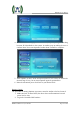
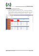
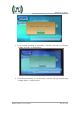
5.2 A/B EXCITER ICON SCREEN
Dual Exciters - Switching Screen: As mentioned above, pressing the “Exc A/B”
icon will bring you to the Dual Exciters Switching Screen, a shown below.
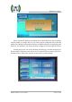
Manual Exciter Switchover: Exciter A is the default on-air exciter. The on-air
exciter’s status will be “GREEN”, as shown in the screen above, indicating that Exciter
B is the current on-air exciter. Pressing the “Exciter A” or “Exciter B” button on this
screen will cause a manual switch between exciters, that is if the Controller is “linked”
to both exciters. (Note: In a dual exciter configuration, both exciters are on at the same
time, producing an RF output signal the same time, and the Controller is considered
“linked” with an exciter when the Controller detects an RF output present from the
exciter as monitored inside the controller).
Auto Exciter Switchover: In a Dual Drive configuration, the TX is set to
automatically switch to the standby exciter in the event a problem occurs with the
on-air exciter. The TX will not automatically switch back to the original Exciter as
long as the standby Exciter is operating properly. However, the TX will
automatically switch back to the original Exciter in the event of a problem with the
on-air (standby) exciter. So the TX will continue to automatically switch to the
standby exciter in the event of a problem with the on-air exciter.
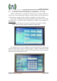
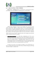
If neither of the exciters can be linked successfully (i.e. the Controller does not
detect a valid RF output present from either exciter), a window will pop up, indicating
“No Exciter Linked”, as shown below.