
User's Manual


MHPTV TX User Manual
MHPTV-USR-DOC-V3.0, 10/18/2019 Page 58 of 148
2. Theory of Operation
The MHPTV transmitter is conceptually simple to understand and easy to
operate.
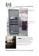
The Transmitter operates on either 240VAC single-phase (3-wire) or 208VAC
three-phase (4-wire) AC Mains service. An AC Mains Distribution compartment is
located on the back-rear floor of the TX. This compartment is shielded for personnel
safety and provides the distribution of appropriate AC power to the various modules
inside the TX cabinet.
A standard ASI input stream is provided to one of the BNC connectors located on
the rear panel of the Exciter. The Exciter (different platforms) supports options for
DVB-ASI and SMPTE310M (ATSC 9x exciter only) stream formats as well as an RF
off-air input via a built-in tuner and TSoIP support via an RJ-45 input. The Exciter
performs the appropriate modulation to produce an RF output at the desired channel
frequency. Exciter configurations may vary – for DTV (ATSC, ATSC 3.0, DVBT/T2,
ISDBT, DTMB, etc.).
The TX supports both Single and Dual Drive (DD) Exciter configurations and
manages the automatic and manual switchover between Exciters in a DD
configuration. The modulated RF output signal from the Exciter(s) is (are) fed into the
Control module which contains a preamp driver stage and built-in N-ways splitter (for
multiple PA configurations). The N-ways outputs of the Controller preamp are then to
feed the RF inputs of each of the PA modules.
The PA modules contain 8 x BLF888E Doherty devices that amplify the RF
signal to produce 1300W of output power per PA. The amplified output signals are
fed into an N-way Hybrid Combiner (for 2/3/4/5/6/8 PAs configuration) and then into
a Directional Coupler (for 2/3/4/5/6/8 PAs configuration) and finally out the top of the
cabinet via a section of 1 5/8 or 3 1/8 transmission line.
The 1 5/8 or 3 1/8 output stack of the Transmitter is then fed into an inline 1 5/8
or 3 1/8 Harmonic Filter (if required) before entering a Before-Filter directional
coupler and the input to the channel mask BPF mounted on top of the cabinet. The
output of the BPF connects through an After-Filter directional coupler into the
Antenna feed to radiate the DTV signal on-air.
The Exciter receives the two feedback signals from the Before-Filter and After-
Filter directional couplers located at the input and output of the BPF. These before and