
User's Manual


MHPTV TX User Manual
MHPTV-USR-DOC-V3.0, 10/18/2019 Page 61 of 148
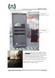
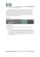
Rear Panel
The rear panel of the Control Unit is shown below:
RF_OUT
Connector: N
Impedance: 50 Ω
Note: Sends pre-amplified RF signal to the inputs of PA modules
RF_IN_A/RF_IN_B
Connector: N
Impedance: 50 Ω
Note: To receive the RF_OUT signal from Exciter_A / Exciter_B
REFL_IN (TX Reflected Power)
Connector: BNC
Impedance: 50 Ω
Note: To receive feedback signal from Directional Coupler for Reflected
Power detection and monitoring.
FWD_IN (TX Forward Power)
Connector: BNC
Impedance: 50 Ω
Note: To receive feedback signal from Directional Coupler for Forward
Power detection and monitoring.
AUX_IN (TX Load Reject Power)
Connector: BNC
Impedance: 50 Ω
Note: To receive a feedback signal from RJCT1 of reject Load for Absorbed
Power detection and monitoring
GPRS (reserved)
ERS485-A/ERS485-B: To be connected to REMOTE of Exciter_A/Exciter_B for
internal communication between exciters and Control Unit.
PRS485: To be connected to the RS485 of PA#1 for internal communication
between the PA module and Control Unit.
CAN: To be connected to the RS485 of PA#2 for internal communication
between the PA module and Control Unit.
RS-232: Reserved.
LAN: 10M/100M Ethernet port for web-based remote control (IP address:
192.168.1.210)
AC INPUT/FUSE: 100-240 VAC
Power Switch: ON/OFF