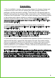
SHOWER TRAY INSTALLATION & CARE GUIDE SB-AZ005WN SB-AZ006WN SB-AZ007WL SB-AZ008WR SB-AZ009WC SB-AZ010WC SB-AZ011WC SB-AZ012WR SB-AZ013WL SB-AZ014WC SB-AZ015WV Have questions? Visit us at www.ANZZI.com or call us at 1-844-44-ANZZI.
Preparation 1. Prior to installation, examine all boxes and packages for shipping damage and compare the piece count with your packing slip. After opening all boxes and packages, read this introduction carefully. Check that all of the needed parts are included in the package by checking offthe components on the "Detailed Diagram of Shower DoorComponents".
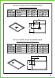
SINGLE THRESHOLD SHOWER BASE Center Drain Configuration SPECIFICATION MODEL D(in) W(in) D1(in) W1(in) SB-AZ011WC 48"X36" 36" 48" 18" 24" SB-AZ014WC 60"X36" 36" 60" 4 4/5" 30 W W1 D1 D SINGLE THRESHOLD SHOWER BASE Left/Right-Hand Drain Configuration MODEL SPECIFICATION D(in) W(in) D1(in) W1(in) SB-AZ007WL 60"X36" 36" 60" 18" 12" SB-AZ013WL 60"X32" 32" 60" 18" 4 4/5" SB-AZ015WV 48"X32" 32" 48" 16" 12" W W1 D1 D 3
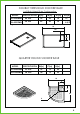
DOUBLE THRESHOLD SHOWER BASE Left/Right-Hand Drain Configuration SPECIFICATION MODEL D(in) W(in) D1(in) W1(in) SB-AZ008WR 60"X36" 36" 60" 18" 12" SB-AZ012WR 60"X36" 36" 60" 18" 4 4/5" W W1 D1 D QUARTER ROUND SHOWER BASE MODEL SPECIFICATION W(in) C(in) R(in) SB-AZ005WN 36"X36" 36" 12" 22" SB-AZ006WN 38"X38" 38" 12" 22" W C C W R 4
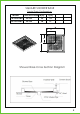
SQUARE SHOWER BASE Center Drain Configuration SPECIFICATION W(in) MODEL C(in) SB-AZ009WC 36"X36" 36" 18" SB-AZ010WC 38"X38" 38" 19" W C C W Shower Base Cross Section Diagram 5
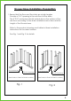
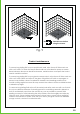
Shower Base Installation-Preparation 1. Ensure that the floor and the studs are at right angles. Provide a 5"×5" opening in the sub-floor for the drain. The 2" PVC waste pipe should extend above the surface of the sub-floor according to the drain installation instructions and the height of the Shower base. Refer to the product drawings and tables in these installation instructions for the drain location. See Fig. 1 and Fig. 2 for details.
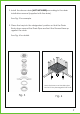
2. Install the shower drain (NOT INCLUDED)according to the drain installation manual (supplied with the drain). See Fig. 3 for example 3. Place the tray into the designated position so that the Drain Body drops around the Drain Pipe and butt the Shower Base up against the studs. See Fig. 4 for details. Lower the base over the drain pipe and set it into placeagainst the studs. Fig. 3 Fig.
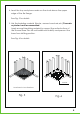
4. Level the tray and place marks on the studs above the upper edge of the tile flange. See Fig. 5 for details. 5. Mix the bedding material (Mortar, cement-sand mix,etc.)Concrete or plaster is not recommended. Apply enough bedding material to support the entire bottom of the shower base.This will add additional stability and prevent the base from shifting position. See Fig. 6 for details. Mortar Level base in two directions Fig. 5 Fig.
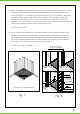
4. After the bedding material has been poured and beforeit sets, place the shower base into the position with the drain assembly sliding over the PVC waste pipe. It will be necessary to push the shower base until the top of the tile flange aligns with the marks drawn on the studs and the front edge is contacting the rough floor along the entire length of the shower base. Ensure that the base is level in all directions.
24 Hours Wait 24 hours before using the shower Fig. 9 Product maintenance To ensure long lasting life for your acrylic back walls, wipe them off after each use with a soft cloth. To clean the acrylic back walls use non-abrasive sprays or cream based cleaners. Never use abrasive cleansers, metal brushes or scrapers that could scratch ordull the surface. To ensure long lasting life for your glass shower products, wipe them off after each use with a soft cloth.