ITEM: SD-AZ013-01**(SD-AZ8077-01**) SD-AZ013-02**(SD-AZ8077-02**) SD-AZ017-01**(SD-AZ8080-01**) ANZZI GLASS SHOWER DOOR INSTALLATION & OPERATION MANUAL V3.0 10/30/2022 SD-AZ13-01** SD-AZ13-02** SD-AZ17-01** V 3.
1
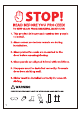
Please check the product for damage and missing parts immediately upon delivery. Damage reported later will not be covered by our warranty. Please handle the product with care. Avoid any impact to the sides and edges of the glass. Consult your local building codes before installation. To reduce the risk of breakage, keep corner protectors on glass while installing. If this unit is being installed in new construction, please install all required plumbing and drainage before installing the shower.
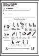
Surface of the threshold or tub deck must be level for proper installation. This model requires a minimum 3.15" (80 mm) flat level threshold or tub deck space for installation. Tools Required . 5/16 This product is heavy and requires two people to install. . Use cut-resistant, non-slip gloves to reduce the risk of personal injury and to hold the glass firmly. This product is heavy and requires two people to install. 3 3/8 (9.
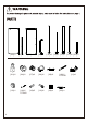
[02]x1 4 [03]x1 [05]x1 [06]x1 [13]x2 [14]x1 [15]x1 [17]x2 [21]x1 [01]x2 [04]x2 [07]x2 [08]x2 [09]x2 [10]x2 ST5x40 [12]x1 [16]x5 ST4x20 [18]x5 [19]x2 [20]x1 [22]x1 [11]x2
Part [01] [02] [03] [04] [05] [06] [07] [08] [09] [10] [11] 5 Description Limit Stop Fixed Panel Support Bar Roller Door Panel Handle Set Fixed Block Wall Bracket White Plastic Anchor 8X36 Screw ST5x40 Allen Keys Qty. 2 1 1 2 1 1 2 2 2 2 1 Part [12] [13] [14] [15] [16] [17] [18] [19] [20] [21] [22] Description Guide Block Water Sealing Strip Rail Cover Bottom Rail Screw ST4X20 Water Sealing Strip Small Anchor 6X28 Roller Guard Silicone Cleaner Glass Bottom Protection Seal Screw Driver Bit Qty.
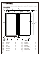
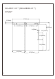
SD-AZ013-01**(SD-AZ8077-01**) 48"x76" 48"[1220mm] 3.3"[84mm] 16.7"[425mm] 18.7"[475mm] 76"[1930mm] 2.4"[60mm] 72.2"[1834mm] 15.8"[400mm] 30.4"[772mm] 23"[585mm] 6 26.
SD-AZ013-02**(SD-AZ8077-02**) 60"x76" 60"[1524mm] 3.3"[84mm] 22.7"[577mm] 24.7"[627mm] 76"[1930mm] 2.4"[60mm] 72.2"[1834mm] 15.8"[400mm] 30.4"[772mm] 29"[737mm] 7 32.
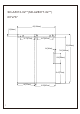
SD-AZ017-01**(SD-AZ8080-01**) 60"x62" 60"[1524mm] 3.3"[84mm] 22.7"[577mm] 24.7"[627mm] 62"[1575mm] 2.4"[60mm] 58.2"[1479mm] 15.8"[400mm] 30.4"[594mm] 29"[737mm] 8 32.
To avoid personal injury or property damage, identify components and read all instructions before installing. This model requires a minimum 3.15" (80mm) of flat level threshold or tub deck space for installation. (Dimension "D" of Fig 1.) 1. Measure the finished opening width at the bottom or tub surface (“W2”) and at the top (“W1”). The height of top: SD-AZ013-01/SD-AZ013-02: H = 72.7" [1847mm]; SD-AZ017-01: H = 58.7" [1491mm].
2 This shower door must be mounted to a stud. Minimum threshold space is required. IMPORTANT: Using a stud finder, ensure the wall intended to hold the door has a stud at the installation point. A stud in this location must be identified to support the support bar in order to proceed with the installation. If there is no stud in the shown area, we recommend employing a qualified contractor to install one. (Fig 2.1) 1. Using a pencil and stud finder to mark the center line of stud.
Bottom Rail [15] NOTE: Make sure the groove pattern on the Bottom Rail [15] is facing upwards. Bottom Rail [15] 2 1/8" 5/16" Anchors [18]. 2 Bottom Rail [15] Screw ST4X20 [16].
4 1. Use a matched Allen Key [11] to stick into the side hole of Fixed Blocks [07] to remove it and the Washers from t he Support Bar [03] and install the Support Bar [03] to the Fixed Panel [02] from b ehind. Slide the Washers onto the Fixed Panel [02] and secure with Fixed Block [07]. (Fig 4.1) Note: Make sure the hole closest to the edge of the Fixed Panel [02] is far away from the wall. There are Gaskets between the Support Bar [03] and the Fixed Panel [02]. 2.
5 1. Hold the Fixed Panel [02] still. Adjust the Fixed Panel [02] and Support Bar [03] to the vertically level and horizontally level. If necessary, loose the Fixed Blocks [07] for the adjustment. Tighten the Fixed Blocks [07] again after the adjustment. (Fig 5.1) 2. Slightly push the Wall Brackets [08] to the wall and mark the outline of it on the wall. T hen, remove the Fixed Panel [02] and Support Bar [03]. (Fig 5.
6 1. Remove Screw, Eccentric Block, and Washer from the Roller [04]. Install the Roller [04] t o the Door Panel [05] as the figure shows. Using one provided small Allen Key [11] to stick into the side hole of Roller [04] and press the Stopper of it. Slightly tighten the Screw by another matched Allen Key [11] to secure the Roller [04]. (Fig 6.1, Fig 6.2) IMPORTANT: Make sure there is Washer between the Roller [04] and the Door Panel [05].
7 1. Make sure there is Glass Bottom Protection Seal [21] at the bottom of Fixed Panel [02] and apply a good quality Silicone Sealant on the bottom of the Glass Bottom Protection Seal [21]. (Fig 7.1) 2. Install the Wall Brackets [08] back to the Support Bar [03]. Install the Fixed Panel [02] to the Bottom Rail [15]. (Fig 7.1) 3. Install the Wall Brackets [08] to the Wall Bracket Plate. Tighten Wall Brackets [08] to secure.
8 1. Draw Center Line 1 at the middle of the threshlod. Draw Center Line 2 parallel to the Bottom Rail [15] and 1.26" from the inner edge of it. Draw lines parallel to Center Line 1 on the left and right at the distance of 0.73". The crosses formed by Center Line 1 and the lines are the position for the drilling in Step 8.2. (Fig 8.1) 2. Drill a 1/8" hole at each marked location if drilling into acrylic or wood material. Drill a 5/16" hole if drilling into tile material and insert the Small Anchors [18].
9 1. Carefully lift up the Door Panel [05] and place the Roller [04] on the Support Bar [03]. (Fig 9.1) 2. Use a matched Allen Key [11] to unscrew the Limit Stop [01] on the door side and adjust it to the position 2.76" minimum away from the wall. Tighten the screw of Limit Stop [01] to secure it. Slightly push the Door Panel [05] to the wall. The Water Sealing Strip [13] should be touched the wall. If it doesn't, adjust the position of the Limit Stop [01] again. (Fig 9.2) 3.
10 1. Disassemble the Roller Guards [19] and install it to the Door Panel [05] as the figure shows. (Fig 10) 2. Install the Rod and one Washer from the front of the Door Panel [05], install the Nut assembly from the back of Door Panel [05]. Hold the Rod by hand and use a matched A llen Key [11] to stick to the side hole of the Nut and tighten it to secure. If the Rod is too close to the Support Bar [03], turn the Nut in counter-clockwise.
11 1. Remove the Corner Protectors and install the Water Sealing Strip [17] to the side of Door Panel [05]. Make sure the end of Water Sealing Strip [17] installed to Door Panel [05] is aligned with the bottom of it. If the Water Sealing Strip [17] is longer than the Door Panel [05] after installation, cut it to correct length. The flange should be faced outside. (Fig 11.1) 2. Remove the Corner Protectors and install the Water Sealing Strip [17] to the side of Fixed Panel [02].
12 1. Disassemble the Handle Set [06] and install to the Door Panel [05]. Install Handle, Flange and Washer from the front of Door Panel [05]. Install Washer, Lever and Fixed Block front the back of Door Panel [05]. (Fig 12.
13 1. Apply a good quality Silicone Sealant at the inner corner form by the Bottom Rail [15] and Threshold, inner corner form by the Bottom Rail [15] and Fixed Panel [02]. (Fig 13) Allow 24 hours for the silicone to Use Silicone cleaner [2 0] to fully cure before using the shower. smooth and clean up the silicone.
LEFT SIDE INSTALLATION The previous steps are for right side installation. For left side installation, please follow the instructions below. 1. Install the shower door by following step 1 through step 3 of the right side installation instructions. Then, flip the Fixed Panel assembly and transpose the Support Bar as in step 4 and install. 2. Transpose the Door Panel [05] as in step 6 and install. 3. Continue by following right side installation steps 5,7-13.