
Installation Guide


9
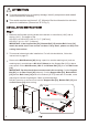
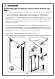
To avoid personal injury or property damage, identify components and read all
instructions before installing.
This model requires a minimum 3.15" (80mm) of flat level threshold or tub deck
space for installation. (Dimension "D" of Fig 1.)
Measure the finished opening width at the bottom or tub surface (“W2”) and at
the top (“W1”). The height of top:
SD-AZ013-01/SD-AZ013-02: H = 72.7" [1847mm];
SD-AZ017-01: H = 58.7" [1491mm].
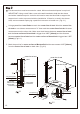
IMPORTANT: If the Support Bar [03], Bottom Rail [15] and the Rail Cover [14]
match the width, there's no need to cut them. If they don't, please see Setp 2 for
cutting instructions.
This manual shows right side installation. For left side installation, follow the
instructions in page 21.
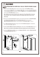
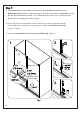
Remove the Wall Brackets [08].Using a pencil or another marking tool (such as
masking tape), mark dis
tance
W1-0.94" (24mm) on the Support Bar [03] (to leave
some space for the Wall Bracket), W2 on the Bottom Rail [15], C on the Rail Cover
[14].
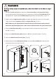
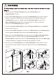
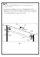
IMPORTANT: Double check the measurements before cutting. Cut the Support
Bar [03] on the Door Panel [05] side only. Cut the Support Bar [03], Bottom Rail
[15] and the Rail Cover [14] with a fine toothed (32 TPI) hack saw. If needed, use a
metal file to smooth rough edges. Clean up metal shavings.
DO NOT stand on or use a vice to hold the Support Bar [03], Bottom Rail [15] and
the Rail Cover [14] while cutting.
1.
2.
3.
1
screws
[08]
C
screws
[03]
[15]
[14]
C
H
D