
Install Instructions
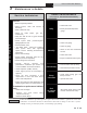
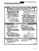

2 Maintenance schedule (continued)
7
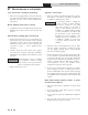
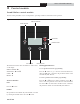
Figure 2-2 Condensate Disposal
User’s Information Manual
Condensate drain
1. This boiler is a high efficiency appliance that produces
condensate.
2. The bottom of the boiler has a 3/4 inch pipe for
connection of a 3/4 inch PVC pipe (FIG. 2-2).
3. Slope condensate tubing down and away from the
boiler into a drain or condensate neutralizing filter.
Condensate from the Combi Boiler will be slightly
acidic (typically with a pH from 3 to 5). Install a
neutralizing filter if required by local codes.
A Neutralizer Kit is available from the factory.
4. Do not expose condensate line to freezing temperatures.
5. Use only plastic tubing or piping as a condensate drain
line (FIG. 2-2).
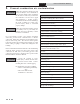
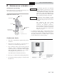
Clean/Inspect Trap Assembly
Remove the clean out cap on the bottom of the trap. Let
the condensate and any debris drain out.
DIR #2000529332 00
HOSE BARB
MOUNTING NUT
FLOAT BALL
CONDENSATE
DRAIN
REMOVABLE CAP
TO CLEAN OUT TRAP
Figure 2-1 Condensate Trap
Use materials approved by the authority
having jurisdiction. In the absence of other
authority, PVC and CPVC pipe must comply
with ASTM D1785 or D2845. Cement and
primer must comply with ASME D2564 or
F493. For Canada use CSA or ULC certified
PVC or CPVC pipe, fittings, and cement.
6. A condensate removal pump is required if the boiler is
below the drain. When installing a condensate pump, select
one approved for use with condensing boilers and furnaces.
The pump should have an overflow switch to prevent
property damage from condensate spillage.
NOTICE
NOTICE
To allow for proper drainage on large
horizontal runs, a second line vent may be
required and tubing size may need to increase
to 1 inch.
The condensate line must remain
unobstructed, allowing free flow of
condensate. If condensate is allowed to
freeze in the line or if the line is obstructed in
any other manner, condensate can exit from
the boiler tee, resulting in potential water
damage to property.
ProLine® XE
Combi Boiler