Instruction Manual COMMERCIAL GAS WATER HEATERS MODELS BTH-120(A)/150(A)/199(A)/250(A) SERIES 200 & 201 500 Tennessee Waltz Parkway Ashland City, TN 37015 www.hotwater.com INSTALLATION - OPERATION - SERVICE - MAINTENANCE - LIMITED WARRANTY WARNING: If the information in these instructions is not followed exactly, a fire or explosion may result causing property damage, personal injury or death.
TABLE OF CONTENTS SAFE INSTALLATION, USE AND SERVICE ����������������������������������������� 3 APPROVALS ������������������������������������������������������������������������������������������ 3 GENERAL SAFETY INFORMATION ������������������������������������������������������ 4 Precautions ���������������������������������������������������������������������������������������� 4 Grounding Instructions ���������������������������������������������������������������������� 4 Hydrogen Gas Flammable ������
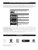
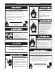
SAFE INSTALLATION, USE AND SERVICE The proper installation, use and servicing of this water heater is extremely important to your safety and the safety of others. Many safety-related messages and instructions have been provided in this manual and on your own water heater to warn you and others of a potential injury hazard. Read and obey all safety messages and instructions throughout this manual.
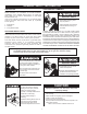
GENERAL SAFETY INFORMATION PRECAUTIONS HYDROGEN GAS FLAMMABLE DO NOT USE THIS WATER HEATER IF ANY PART HAS BEEN EXPOSED TO FLOODING OR WATER DAMAGE. Immediately call a qualified service agency to inspect the water heater and to make a determination on what steps should be taken next. Explosion Hazard If the unit is exposed to the following, do not operate heater until all corrective steps have been made by a qualified service agency. Flammable hydrogen gases may be present. 1. External fire.
GENERAL SAFETY INFORMATION Fire or Explosion Hazard Fire Hazard Do not store or use gasoline or other flammable vapors and liquids in the vicinity of this or any other appliance. For continued protection against risk of fire: Avoid all ignition sources if you smell gas. Do not expose water heater controls to excessive gas pressure. Do not install water heater on carpeted floor. Do not operate water heater if exposed to flooding or water damage. Use only the gas shown on the water heater rating label.
INTRODUCTION Thank You for purchasing this water heater. Properly installed and maintained, it should give you years of trouble free service. Detailed installation diagrams are also found in this manual. These diagrams will serve to provide the installer with a reference. It is essential that all venting, water piping, gas piping and wiring be installed as shown.
FEATURES AND COMPONENTS BASIC OPERATION MODULATION The water heaters covered in this manual have a helical coil shaped heat exchanger that is submerged in the storage tank. The water heater’s Main Burner is a radial design burner, it is mounted on the top and fires downward through the heat exchanger. This is a forced draft burner; hot burning gases are forced through the heat exchanger under pressure and exit through the exhaust/vent connection located at the bottom of the water heater.
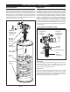
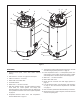
TOP VIEW 6 5 2 8 9 11 18 2 4 13 3 7 12 10 14 16 17 1 15 FRONT TOP VIEW OF ALL MODELS Figure 3 COMPONENTS (All Models) gas pressure is above minimum requirements. The control system monitors this switch and will disable heating operation if its contacts are open during a heating cycle. See Gas Pressure Requirements and Table 3 on page 11. 10. Vent connection (exhaust / condensate elbow) - three inch aluminum. 11. Intake air connection - 3 inch PVC. 12. Blocked Exhaust (vent) switch.
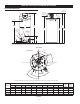
3 4 5 2 6 4 5 13 14 3 7 16 2 8 9 15 1 10 1 15 11 12 LEFT SIDE RIGHT SIDE Figure 4 9. Temperature-Pressure Relief Valve discharge pipe - see T&P Valve Discharge Pipe Requirements: on page 15. SIDE VIEWS 1. Cleanout access panel, covers water heater cleanout opening. 10. Lower Temperature Probe, 1 of 2 temperature probes. The water heater’s control system monitors this probe to detect water temperature in the lower portion of the storage tank. 2.
INSTALLATION CONSIDERATIONS ROUGH IN DIMENSIONS SUPPLY GAS CONNECTION INTAKE AIR CONNECTION 3 INCH PVC WATER OUTLET HEIGHT T & P VALVE FRONT D BACK B LOWER TEMPERATURE PROBE CLEANOUT E E I 3/4” NPT RECIRCULATION RETURN F H VENT CONNECTION 3 INCH PVC (exhaust elbow) 1 1/2” NPT WATER INLET 3/4” NPT DRAIN C J G A These designs comply with the current edition of the American National Standard for Gas Water Heaters, Volume III, ANSI Z21.10.3 / CSA 4.
GAS LINE CONNECTION SIZE STORAGE CAPACITIES TABLE 1 TABLE 2 † MODEL BTH 120 BTH 150 BTH 199 BTH 250 SERIES 200/201 200/201 200/201 200/201 NATURAL GAS 3/4 "NPT 3/4 "NPT 3/4 "NPT 3/4 "NPT PROPANE GAS 3/4 "NPT 3/4 "NPT 3/4 "NPT 3/4 "NPT MODEL BTH 120 BTH 150 BTH 199 BTH 250 U. S.
There is a risk in using fuel burning appliances such as gas water heaters in rooms, garages or other areas where gasoline, other flammable liquids or engine driven equipment or vehicles are stored, operated or repaired. Flammable vapors are heavy and travel along the floor and may be ignited by the water heater’s igniter or Main Burner flames causing fire or explosion.
combustion, potentially resulting in fire, asphyxiation, serious personal injury or death. • DO NOT cover the instruction manual. Keep it on the side of the water heater or nearby for future reference. • DO NOT apply insulation to the top of the water heater, as this will interfere with safe operation of the blower assembly. • DO obtain new warning and instruction labels from the manufacturer for placement on the blanket directly over the existing labels.
MIXING VALVES HOT WATER OUTLET Water temperature over 125°F (52°C) can cause severe burns instantly resulting in severe injury or death. 12” TO 15” (30-38 cm) Children, the elderly and the physically or mentally disabled are at highest risk for scald injury. TEMPERED WATER OUTLET Feel water before bathing or showering. Temperature limiting devices such as mixing valves must be installed when required by codes and to ensure safe temperatures at fixtures.
TEMPERATURE-PRESSURE RELIEF VALVE water in adequate quantities should circumstances demand. If the discharge pipe is not connected to a drain or other suitable means, the water flow may cause property damage. CAUTION Explosion Hazard Water Damage Hazard Temperature-Pressure Relief Valve must comply with ANSI Z21.22CSA 4.4 and ASME code. • Temperature-Pressure Relief Valve discharge pipe must terminate at adequate drain.
CONDENSATE DRAIN line, such as copper, to the water heater for this reason. See Condensate Drain Installation on page 39. The water heaters covered in this manual are condensing appliances and require a building drain to be located in close proximity to allow the condensate to drain safely. COMBUSTIBLE MATERIAL STORAGE Condensate drains from the water heater at the exhaust elbow located at the bottom.
AIR REQUIREMENTS UNUSUALLY TIGHT CONSTRUCTION In unconfined spaces in buildings, infiltration may be adequate to provide air for combustion, ventilation and dilution of flue gases. However, in buildings of unusually tight construction (for example, weather stripping, heavily insulated, caulked, vapor barrier, etc.) additional air must be provided using the methods described in the Confined Space section that follows.
FRESH AIR OPENINGS FOR CONFINED SPACES Alternatively a single permanent opening, commencing within 12 inches (300 mm) of the top of the enclosure, shall be provided. See Figure 10. The water heater shall have clearances of at least 1 inch (25 mm) from the sides and back and 6 inches (l50 mm) from the front of the water heater.
OUTDOOR AIR THROUGH TWO VERTICAL DUCTS When ducts are used, they shall be of the same cross sectional area as the free area of the openings to which they connect. The minimum dimension of rectangular air ducts shall be not less than 3 inches (7.62 cm). The illustrations shown in this section of the manual are a reference for the openings that provide fresh air into confined spaces only. AIR FROM OTHER INDOOR SPACES DO NOT refer to these illustrations for the purpose of vent installation.
INSTALLATION REQUIREMENTS - COMMONWEALTH OF MASSACHUSETTS COMMONWEALTH OF MASSACHUSETTS INSPECTION For all side wall terminated, horizontally vented power vent, direct vent, and power direct vent gas fueled water heaters installed in every dwelling, building or structure used in whole or in part for residential purposes, including those owned or operated by the Commonwealth and where the side wall exhaust vent termination is less than seven (7) feet above finished grade in the area of the venting, includi
VENTING INSTALLATION discharge all flue gases to the outdoor atmosphere through a sealed vent (exhaust) pipe. Direct Vent configurations have two pipes connected to the water heater, one vent pipe and one intake air pipe. Direct Vent configurations can be terminated in one of seven different arrangements. See Figure 44 on page 35 through Figure 50 on page 36. Breathing Hazard - Carbon Monoxide Gas • Install vent system in accordance with codes.
18. Stress levels in pipe/fittings can be significantly increased by improper installation. If rigid pipe clamps are used to hold the pipe in place, or if the pipe cannot move freely through a wall penetration, the pipe may be stressed, or high thermal stresses may be formed when the pipe heats up and expands. Install accordingly to minimize such stresses.
NOTE: Refer to Tables 9 and 10 on page 29 for the equivalent linear pipe length of AL29-4C® 45° and 90° elbows. FACTORY SUPPLIED FITTINGS The water heater ships with two (2) factory supplied 3 inch terminations (PVC 45° elbows with debris screen). Factory supplied vent and intake air terminations, concentric, or low profile terminations must be used.
If the vent piping will terminate vertically, through a roof, see Vertical Termination Installation on page 25. If a concentric termination(s) will be used see Concentric Termination Installation on page 30. If the vent piping will terminate horizontally, through a sidewall, see Sidewall Termination Installation on page 27. If a low-profile termination will be used see Low Profile Termination Installation on page 34. 6.
VERTICAL TERMINATION INSTALLATION INTAKE AIR SCREEN 1. Determine the location for the termination(s). 2. If installing only the vent (exhaust) piping in a Power Vent configuration vertically through the roof; ensure that all exterior vertical clearance requirements shown in Figure 22 and Figure 23 on page 26 are being maintained. These clearances and those cited by local and national codes must be maintained.
8. Suspend the pipe(s) through center of hole using field supplied metal strapping or equivalent support materials as shown in Figure 22 on page 26. IF LESS THAN 10 FEET (3 m) 9. Slide a roof boot or equivalent flashing over the pipe and secure roof boot or equivalent flashing to roof and seal around the flashing as shown in Figure 22, Figure 23 and Figure 24 on page 26. 24 INCHES (60 cm) MINIMUM HEIGHT ABOVE 10.
SIDEWALL TERMINATION INSTALLATION 18. Cut a 4 inch (10 cm) diameter hole for 3 inch pipe or 5 inch (13 cm) diameter hole for 4 inch pipe where the pipe(s) will pass through the wall. 12. Determine the location for the termination(s). 13. If installing only vent (exhaust) piping in a Power Vent configuration through a sidewall; ensure that all exterior sidewall clearance requirements for the termination, shown in Figure 51 on page 37, are being maintained.
POLYPROPYLENE INSTALLATIONS Polypropylene vent systems do not use cement to connect the pipe and elbow sections but use a push together gasket seal method. Do not attempt to connect Polypropylene with sealant cement. All vent connections MUST be secured by the vent manufacturer’s joint connector. The installer must use a specific vent starter adapter at the flue connection. The adapter is supplied by the vent manufacturer to adapt to its vent system.
AL29-4C ® VENT INSTALLATIONS The water heaters covered by this manual are approved to be installed using the approved vent terminations shown in this manual. This means that, the installer must use the adapter listed in Tables 9 and 10 and a short piece of PVC pipe to complete the end of the vent system with an approved termination. In Canada, the PVC pipe length must be listed to ULC636. (AL29-4C® is a registered trademark of Allegheny Technologies, Inc.
CONCENTRIC TERMINATION INSTALLATION NOTE: If this required 10 foot (3 m) distance to a parapet, vertical wall or structure cannot be maintained, standard terminations must be used. See Vertical Termination Installation on page 25. 1. Concentric terminations must be ordered separately. BTH 120 - 250 models must use the 4 inch concentric termination; Part Number: 9006328005.
4 INCH CONCENTRIC TERMINATION INSTALLATION INTAKE AIR CONNECTION 3 INCH PVC 3” x 3” x 4” Y FITTING When installing 4 inch intake air and vent pipe - connect the piping to the concentric termination using field supplied 4" x 3" reducer couplings and short sections of 3 inch pipe (18 inches or less) pipe. Cement all fittings and pipe in place. INTAKE AIR PIPE VENT CONNECTION - 3 INCH PVC VENT PIPE 9.
MULTIPLE CONCENTRIC TERMINATION CLEARANCES Four Concentric Terminations When installing multiple concentric terminations vertically through a roof or horizontally through a sidewall ensure the required clearances (separation) between terminations are maintained. Ensure multiple terminations are arranged or grouped as required. 1.
MULTIPLE CONCENTRIC TERMINATION ARRANGEMENTS SIDEWALL The illustrations on this page show some of the installation arrangements for multiple concentric terminations that are allowed. See Multiple Concentric Termination Clearances on page 32 for detailed information on clearances and additional arrangement options. NOTE: When multiple concentric terminations are installed through a roof in the same location all termination caps must be at the same height measured from the ground.
LOW PROFILE VENT INSTALLATION To Heater Intake Air Connection This water heater is certified for sidewall direct venting with IPEX System 636 Low Profile Vent Kit. Follow instructions below for proper installations. From Heater Vent Pipe Connection All termination kits must be located and installed in accordance with locl building code and CSA B149.1 Natural Gas and Propane Installation Code. 12” Min to OverHang Possible Orientations 1.
VENTING ARRANGEMENTS Power Vent Vertical Figure 42 Power Vent Horizontal Figure 43 Direct Vent Vertical Figure 44 Direct Vent Horizontal Figure 45 Direct Vent Vertical Vent Horizontal Intake Figure 46 Direct Vent Horizontal Vent Vertical Intake Figure 47 35
VENTING ARRANGEMENTS Direct Vent Vertical Concentric Figure 48 Direct Vent Horizontal Concentric Figure 49 36 Direct Vent Horizontal Low Profile Figure 50
TERMINATION CLEARANCES SIDEWALL POWER VENT POWER VENT (using room air for combustion) EXTERIOR CLEARANCES FOR SIDEWALL VENT TERMINATION G V D H A v E L v B FI XE D CLOSED V F OPERABLE V B B C OPERABLE V B B FI XE D CLOSED V M X V K J A X V B V X VENT TERMINAL AIR SUPPLY INLET AREA WHERE TERMINAL IS NOT PERMITTED Figure 51 Vent terminal clearances for “Power Vent” installations. Power Vent configurations use room air for combustion.
TERMINATION CLEARANCES SIDEWALL DIRECT VENT DIRECT VENT (using outdoor air for combustion) EXTERIOR CLEARANCES FOR SIDEWALL VENT TERMINATION G V D H A v E L v B FI XE D CLOSED V F B B C OPERABLE V OPERABLE V B B FI XE D CLOSED V M X V K J A X V B V VENT TERMINAL X AIR SUPPLY INLET AREA WHERE TERMINAL IS NOT PERMITTED Figure 52 Vent terminal clearances for “Direct Vent” installations. Direct Vent configurations use outdoor air for combustion.
WATER HEATER INSTALLATION CONDENSATE DRAIN INSTALLATION 3. Terminate the condensate drain piping with an elbow above the drain. Ensure that any discharge will exit the condensate drain line no more than 6 inches (15.2 cm) above a suitable building drain, or external to the building, see Figure 53. Installation must conform with these instructions and local building codes. Field supplied materials required for installation include: • Approved PVC cement and PVC primer.
SUPPLY GAS LINE INSTALLATION GAS LINE SIZING Depending on the developed equivalent length and/or the number of appliances connected to a common main, the size of supply gas lines may have to be increased. Contact your local gas utility company to ensure that adequate gas service is available and to review applicable installation codes for your area. Size the supply/main gas line(s) in accordance with Table 11 or Table 12.
GAS LINE CONNECTION NOTE: Should overheating occur or the gas supply fail to shut off, turn off the Main Gas Shutoff valve to the water heater. 1. The water heaters covered by this manual are shipped from the factory with 3/4 inch supply gas connections. The supply gas line must not be smaller than 3/4 inch. Connect the supply gas line to the water heater's 24 Volt Gas Valve in accordance with all applicable local and national code requirements. GAS LINE LEAK TESTING 2.
POWER SUPPLY CONNECTIONS heating operation during periods when the building is unoccupied or there is no demand for hotwater. Read the requirements for the Power Supply on page 13 before connecting power. To use the enable/disable circuit it must first be activated by selecting the “Use External Enable” from the UIM. Field supplied wiring is then installed between the water heater’s CCB and a set of “dry contacts” (no voltage or load) on the field supplied external control.
WATER LINE CONNECTIONS T&P VALVE DISCHARGE PIPE The water piping installation must conform to these instructions and to all local and national code authority having jurisdiction. Good practice requires that all heavy piping be supported. Read and observe all requirements in the following sections before installation of the water piping begins: Explosion Hazard 1. Mixing Valves on page 14. Temperature-Pressure Relief Valve must comply with ANSI Z21.22CSA 4.4 and ASME code. 2.
TEMPERATURE REGULATION HIGH TEMPERATURE LIMIT CONTROL (ECO) TABLE 13 This water heater is equipped with an ECO (energy cut out) non adjustable high temperature limit switch. The ECO is a normally closed switch that opens (activates) on a rise in temperature. The ECO is located inside the Upper Temperature Probe (two red wires), see pages 8 and 9 for location. The ECO switch contacts will open when the water temperature reaches approximately 202°F (94°C) and close at approximately 140°F (49°C).
CONTROL SYSTEM OPERATION OVERVIEW user input buttons; an up, down and three (3) multi functional operational buttons below the LCD, see Figure 59. The water heaters covered in this manual are equipped with an electronic control system that regulates water temperature inside the storage tank. Heating cycles and ignition are managed by the control system. The ECO (energy cut out), flame sensor, pressure switches and temperature probes are monitored by the control system.
STATUS ICONS The Status Icons are displayed on the Desktop screen and convey operational and diagnostic information. The icons are described in the table below. See Figure 59 on page 45 and the Sequence Of Operation on page 57. TABLE 14 Icon Description Water temperature in the tank has fallen. Shaded area of the animated thermometer icon will rise and fall in response to water temperature in the storage tank as sensed from the Upper and Lower Temperature Probes.
OPERATING STATES The current operational state of the water heater is displayed on the Desktop screen as the "Status." The common operational states are described in the table below. See Figure 59 on page 45 and the Sequence Of Operation on page 57. TABLE 15 State Description Standby The water heater is not in an active heating cycle. IE: the Tank Temperature is at or above the Operating Set Point.
USER SETTINGS & CONTROL SYSTEM MENUS TEMPERATURES MENU Operating Set Point And Differential Adjustment The Operating Set Point is adjustable from 90°F (42°C) to 180°F (82°C). The factory setting is 120°F (49°C). The Differential is adjustable from 2° to 20°. The factory setting is 8°. These user settings are accessed from the Temperatures menu. The following instructions will explain how to adjust these settings and navigate the control system menus.
TEMPERATURES MENU (CONT) DESCRIPTION/ACTION DISPLAY • Differential - Adjustable user setting that changes the tank temperature differential with a range of 2° to 20°F. The factory setting is 8°F. • Tank Temperature - non adjustable - control system sensed temperature (averaged from upper and lower temperature probes). • Upper Temperature - non adjustable - control system sensed temperature from the Upper Temperature Probe.
DISPLAY SETTINGS DESCRIPTION/ACTION DISPLAY Select Display Settings from the Main Menu and press the Operational Button under "SELECT" to enter this menu. This menu contains adjustable display options for viewing information on the UIM’s LCD screen. Use the Up & Down Buttons to navigate the menu. Display Settings • Temperature Units - Adjustable user setting that changes temperature units display to Celsius °C or Fahrenheit °F.
CURRENT FAULT DESCRIPTION/ACTION DISPLAY Select Current Fault from the Main Menu and press the Operational Button under "SELECT" to enter this menu. This menu contains non adjustable operational information. Use the Up & Down Buttons to navigate the menu. Blocked Exhaust This menu contains the current Fault or Alert error message. The time the Fault or Alert message occurred appears directly below. A brief description of what causes the particular Fault or Alert condition appears below that.
SERVICE CONTACT INFORMATION The control system has a discrete menu that Installing contractors and/or service agents can access to enter contact information for their customers. This contact information will be displayed with all Fault and Alert messages. DESCRIPTION/ACTION DISPLAY From the Desktop Screen (see Figure 59 on page 45) press and hold down the middle (unmarked) Operational Button for 30 seconds and then release it.
START UP PRIOR TO START UP port one full turn only; turn the needle valve screw counterclockwise to open the valve. Slide the manometer sensing tube over the top of the test port, see Figure 60 and Figure 61. Installation and start up of this water heater requires abilities and skills equivalent to that of a licensed tradesman in the field involved, see Qualifications on page 6. 6.
LIGHTING THE WATER HEATER LIGHTING & OPERATION LABELS The instruction label below is affixed to the water heater's covered by this manual at the factory and must be followed when lighting and operating the water heater. FOR YOUR SAFETY READ BEFORE LIGHTING WARNING: If you do not follow these instructions exactly, a fire or explosion may result causing property damage, personal injury or loss of life. FLAMMABLE BEFORE OPERATING: ENTIRE SYSTEM MUST BE FILLED WITH WATER AND AIR PURGED FROM ALL LINES.
SUPPLY GAS PRESSURE ADJUSTMENT with other gas fired appliances; the supply gas pressures shall be measured at each water heater with all gas fired appliances connected to a common main firing at full capacity.
CHECKING THE FIRING RATE HIGH ALTITUDE INSTALLATIONS If firing rate adjustment is required follow these instructions to determine the actual firing rate of the water heater: NOTE: The heaters covered by this manual are capable of modulating their firing rate. The firing rate should be checked with the heater operating at it's full firing rate. Fire and Explosion Hazard Under no circumstances should the input exceed the rate shown on the water heater’s rating label.
TROUBLESHOOTING INSTALLATION CHECKLIST SEQUENCE OF OPERATION The list below represents some of the most critical installation requirements that, when overlooked, often result in operational problems, down time and needless parts replacement. This is not a complete list. Before performing any troubleshooting procedures use the list below to check for installation errors. Costs to correct installation errors are not covered under the limited warranty.
SEQUENCE OF OPERATION FLOW CHART Sequence is shown with Enable/Disable Switch in the Enable position If tank temperature drops below Operating Set Point minus Differential setting a heating cycle is activated Control System performs diagnostic checks Normal State of all pressure switches and ECO are checked Blower Prover pressure switch verified open All other pressure switches and ECO are verified closed NO Control System Locks Out Displays Fault Msg Combustion Blower is energized Pre-Purge cycle Blow
OPERATIONAL PROBLEMS • Vent (exhaust) gas recirculation at the vent and intake air pipe terminations on Direct Vent installations - see Direct Vent Installation on page 24. • Excessive equivalent lengths of intake air and/or vent (exhaust) piping installed - see Venting Requirements on page 22. • Debris clogging/blocking the intake air screen(s) - see Figure 18 on page 25 and Figure 25 on page 27. • Debris clogging/blocking the Main Burner - see Figure 2 on page 7.
• Sediment or lime scale accumulation may be affecting water heater operation. See Maintenance on page 63 for sediment and lime scale removal procedures. • Water heater not firing at full input rating. Check actual firing rate of the water heater, see instructions on page 56. Note that the water heaters covered by this manual are capable of modulating their firing rate. The firing rate is dictated by the hot water draw and various other temperature limitations.
FAULT AND ALERT MESSAGES Call the technical support phone number listed on the back cover for further technical assistance or to locate a qualified service agent in your area. POSSIBLE CAUSES - CHECK/REPAIR DISPLAYED FAULT/ALERT MESSAGE • Using a manometer, ensure that gas supply pressure is above minimum requirement listed on heater’s data plate and does not drop more than 1.5” W.C. when unit fires. • Ensure wire connections to gas valve are clean and tight.
FAULT AND ALERT MESSAGES (CONT) Call the technical support phone number listed on the back cover for further technical assistance or to locate a qualified service agent in your area. POSSIBLE CAUSES - CHECK/REPAIR DISPLAYED FAULT/ALERT MESSAGE • Ensure excessive wind is not pressurizing the intake air or exhaust pipe. • Confirm wire connections of the blower prover switch are clean, tight, and not jumped/shorted. • Use multi-meter to check continuity/resistance of blower prover pressure switch.
MAINTENANCE GENERAL MAINTENANCE SCHEDULE Do not have any combustible materials (such as gasoline, flammable liquids or flammable vapors) within the water heater area. See Locating The Water Heater on page 11. TABLE 17 COMPONENT Tank Water heater maintenance includes periodic tank flushing and cleaning, and removal of lime scale. The water heater should be inspected and adjusted to maintain proper combustion. See Initial Start Up on page 53. A periodic inspection of the venting system should be made.
5. Ensure the drain hose is secured before and during the entire flushing procedure. Flushing is performed with system water pressure applied to the water heater. TANK CLEANOUT OPENING 6. Open the water heater drain valve to flush the storage tank. 7. Flush the water heater storage tank to remove sediment and allow the water to flow until it runs clean. CLEANOUT ACCESS PANEL CLEANOUT GASKET 8. Close the water heater drain valve when flushing is completed. 9. Remove the drain hose. 10.
TABLE 18 TEMPERATURE-PRESSURE RELIEF VALVE UN-LIME® PROFESSIONAL DELIMER Part Number Description 9005416105 4 - 1 gallon (case) 9005417105 1 - 5 gallon POWERED ANODE RODS To insure a long, trouble-free operating life, the water heaters covered in this manual are factory equipped with a powered anode system. The anode rod(s) are of a permanent design and do not need replacing unless damaged. Inspection and cleaning should be performed once a year.
DIAGRAMS CCB - CENTRAL CONTROL BOARD LAYOUT 6 5 4 J16 3 2 1 J13 J3 8 7 6 5 J5 4 3 2 1 J9 4 7 8 9 10 11 12 3 1 2 3 J14 4 5 6 3 1 4 2 J15 8 5 4 3 2 1 2 1 J4 4 3 2 J10 1 2 J17 6 5 1 4 3 2 1 1 8 7 9 4 6 J1 1 3 J12 3 2 1 2 J6 4 3 2 1 Figure 66 66 6 5 4
WIRING DIAGRAM Splice 1 Blue No factory connections Ferrite Bead 6 White/Green 5 Orange 4 Blue White / Blue 2 White/Blue 1 White/Red White / Red CCB J16 Low Voltage In Transformer Transformer Secondary White Transformer Primary Black Neutral 1 Red 2 Black 120V ECO Thermistor Thermistor ECO Dgnd 5VDC 12VDC 24VAC 24VAC Thermistor Thermistor 1 Red 2 Black 3 Black 4 Red 1 Black 2 Black Spark Rod Outlet Pressure Switch Lower Temperature Probe Black Black Inlet Pressure Switch Blower Prove
CIRCULATION PUMP WIRING DIAGRAMS CIRCULATING PUMP WIRING DIAGRAM STORAGE TANK OR BUILDING RECIRCULATION NOTE: USE SEPARATE 120 VAC POWER SUPPLY FOR PUMP CIRCUIT. DO NOT SHARE POWER WITH WATER HEATER AS THIS MAY CAUSE ELECTRICAL LINE NOISE AND LEAD TO ERRATIC CONTROL SYSTEM OPERATION.
HOT WATER TO FIXTURES EXPANSION TANK COLD WATER SUPPLY WATER FLOW SWITCH FULL PORT BALL VALVE CIRCULATING PUMP HOT WATER RETURN TEMPERATURE GAGE DRAIN PRESSURE RELIEF VALVE CHECK VALVE TEMPERATURE CONTROL PROBE TEMPERATURE & PRESSURE RELIEF VALVE LEGEND 7. If a pump is being installed in a recirculation loop between the water heater and a commercial dishwasher wire according to Figure 68 or Figure 69 on page 68. 6.
EXPANSION TANK TEMPERED WATER OUTLET HOT WATER RETURN OUTLET PIPE T&P TO OPEN DRAIN COLD HOT CIRCULATING PUMP PRESSURE RELIEF VALVE TEMPERATURE & PRESSURE RELIEF VALVE MIXING VALVE FULL PORT BALL VALVE DRAIN TEMPERATURE CONTROL PROBE LEGEND WATER FLOW SWITCH TEMPERATURE GAGE CHECK VALVE 7. If a pump is being installed in a recirculation loop between the water heater and a commercial dishwasher wire according to Figure 68 or Figure 69 on page 68. 6.
ALT. COLD WATER CONNECTION EXPANSION TANK COLD WATER SUPPLY HOT WATER RETURN WATER FLOW SWITCH FULL PORT BALL VALVE CIRCULATING PUMP HOT WATER TO FIXTURES TEMPERATURE GAGE CHECK VALVE DRAIN TEMPERATURE CONTROL PROBE PRESSURE RELIEF VALVE TEMPERATURE & PRESSURE RELIEF VALVE LEGEND 7. If a pump is being installed in a recirculation loop between the water heater and a commercial dishwasher wire according to Figure 68 or Figure 69 on page 68. 6.
ALTERNATE LOCATION EXPANSION TANK COLD WATER SUPPLY CIRCULATING PUMP HOT WATER RETURN WATER FLOW SWITCH FULL PORT BALL VALVE CIRCULATING PUMP HOT WATER TO FIXTURES TEMPERATURE GAGE CHECK VALVE DRAIN TEMPERATURE CONTROL PROBE PRESSURE RELIEF VALVE TEMPERATURE & PRESSURE RELIEF VALVE LEGEND 7. If a pump is being installed in a recirculation loop between the water heater and a commercial dishwasher wire according to Figure 68 or Figure 69 on page 68. 6.
PIPE T&P TO OPEN DRAIN EXPANSION TANK COLD WATER SUPPLY WATER FLOW SWITCH FULL PORT BALL VALVE CIRCULATING PUMP HOT WATER RETURN TEMPERATURE GAGE DRAIN PRESSURE RELIEF VALVE CHECK VALVE TEMPERATURE CONTROL PROBE TEMPERATURE & PRESSURE RELIEF VALVE LEGEND 7. If a pump is being installed in a recirculation loop between the water heater and a commercial dishwasher wire according to Figure 68 or Figure 69 on page 68. 6.
PIPE T&P TO OPEN DRAIN PIPE T&P TO OPEN DRAIN WATER FLOW SWITCH FULL PORT BALL VALVE CIRCULATING PUMP EXPANSION TANK COLD WATER SUPPLY HOT WATER RETURN TEMPERATURE GAGE DRAIN PRESSURE RELIEF VALVE CHECK VALVE TEMPERATURE CONTROL PROBE TEMPERATURE & PRESSURE RELIEF VALVE LEGEND 7. If a pump is being installed in a recirculation loop between the water heater and a commercial dishwasher wire according to Figure 68 or Figure 69 on page 68. 6.
PIPE T&P TO OPEN DRAIN PIPE T&P TO OPEN DRAIN PIPE T&P TO OPEN DRAIN WATER FLOW SWITCH FULL PORT BALL VALVE CIRCULATING PUMP EXPANSION TANK COLD WATER SUPPLY HOT WATER RETURN TANK TEMPERATURE CONTROL TEMPERATURE GAGE DRAIN PRESSURE RELIEF VALVE CHECK VALVE TEMPERATURE CONTROL PROBE TEMPERATURE & PRESSURE RELIEF VALVE LEGEND 7. If a pump is being installed in a recirculation loop between the water heater and a commercial dishwasher wire according to Figure 68 or Figure 69 on page 68. 6.
NOTES 76
NOTES 77
NOTES 78
COMMERCIAL WATER HEATER LIMITED WARRANTY EFFECTIVE WHAT'S NOT COVERED For 3 Years, in the event of a tank leak, we will repair or, at our discretion, replace the defective water heater. • Problems caused by improper: gas supply line sizing, gas type, venting, connections, combustion air, voltage, wiring, or fusing For 1 Year, in the event of part failure, we will repair or, at our • Failure to follow applicable codes discretion, replace the defective part.
500 Tennessee Waltz Parkway, Ashland City, TN 37015 Technical Support: 800-527-1953 • Parts: 800-433-2545 www.hotwater.com Copyright © 2014 A. O. Smith, All rights reserved.