
Install Instructions
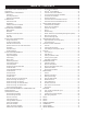
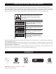
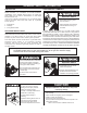
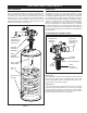
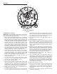
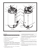
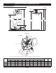
Table Of Contents
- Safe Installation, Use and Service
- APPROVALS
- General Safety Information
- Introduction
- Features And Components
- Installation Considerations
- Installation Requirements
- Gas Supply Systems
- Supply Gas Regulator
- Power Supply
- Mixing Valves
- Dishwashing Machines
- Closed Water Systems
- Thermal Expansion
- Temperature-Pressure Relief Valve
- Condensate Drain
- Combustible Material Storage
- Contaminated Air
- Air Requirements
- Unconfined Space
- Confined Space
- Fresh Air Openings For Confined Spaces
- Outdoor Air Through Two Openings
- Outdoor Air Through One Opening
- Outdoor Air Through Two Horizontal Ducts
- Outdoor Air Through Two Vertical Ducts
- Air From Other Indoor Spaces
- Installation Requirements - Commonwealth of Massachusetts
- Venting Installation
- General Venting Information
- General Venting Instructions
- Intake Air Connection
- Venting Requirements
- Venting Installation Sequence
- Power Vent Installation
- Direct Vent Installation
- Vertical Termination Installation
- Sidewall Termination Installation
- Polypropylene Installations
- Al29-4C® Vent Installations
- Concentric Termination Installation
- 4 Inch Concentric Termination Installation
- Low Profile Vent installation
- Venting Arrangements
- Termination Clearances Sidewall Power Vent
- Termination Clearances Sidewall Direct Vent
- Water Heater Installation
- Temperature Regulation
- Control System Operation
- Start Up
- Troubleshooting
- Maintenance
- Diagrams
- notes
- notes
- notes
- Service Inquiries:
- Commercial
- Water Heater
- Limited Warranty

7
BASIC OPERATION
The water heaters covered in this manual have a helical coil
shaped heat exchanger that is submerged in the storage tank.
The water heater’s Main Burner is a radial design burner, it
is mounted on the top and res downward through the heat
exchanger. This is a forced draft burner; hot burning gases are
forced through the heat exchanger under pressure and exit
through the exhaust/vent connection located at the bottom of the
water heater. See Figure 1 and Figure 2.
INTAKE AIR
(combustion air)
CONNECTION
3 INCH PVC
MAIN
BURNER
(radial design)
BLOWER
BURNER
ASSEMBLY
HEAT
EXCHANGER
HELICAL
COIL
VENT (exhaust)
OUTLET
Figure 1
FEATURES AND COMPONENTS
MODULATION
The water heaters covered by this manual are capable of
modulating their ring rate. The CCB monitors the water
temperature in the tank and regulates the ring rate to achieve
the target temperature setpoint. The ring rate is dictated by
the hot water draw, proximity to the tank temperature setpoint,
and various other temperature limitations. Periodically, when the
heater is in modulation mode, the CCB will increase the blower
speed for a short period of time to clear out any condensation
that has accumulated in the heat exchanger then decreases
the blower speed back to the modulating ring rate required to
maintain the desired tank temperature setpoint. This ramping up
and down of the blower speed is considered normal operation of
the water heater.
BLOWER/BURNER ASSEMBLY DETAIL
COMBUSTION
BLOWER
ASSEMBLY
FLAME
SENSOR
SPARK IGNITER
MAIN
BURNER
(radial design)
BURNER
FLANGE
INTAKE AIR
(combustion air)
CONNECTION
3 INCH PVC
Figure 2
Spark Igniter
The control system energizes the spark ignition control with 120
VAC during the ignition cycle. The spark ignition control then
sends a high-voltage current to the spark igniter which in turn
ignites the main burner air/gas mixture.
Flame Sensor
The control system also monitors the ame sensor to conrm
a ame is present at the Main Burner. If a ame is not veried
during the ignition trial period (3-5 seconds) the control system
will immediately de-energize the 24 Volt Gas Valve. See the
Sequence Of Operation Flow Chart on page 58.