
Install Instructions
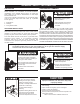
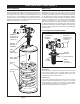
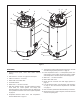
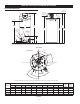
Table Of Contents
- Safe Installation, Use and Service
- APPROVALS
- General Safety Information
- Introduction
- Features And Components
- Installation Considerations
- Installation Requirements
- Gas Supply Systems
- Supply Gas Regulator
- Power Supply
- Mixing Valves
- Dishwashing Machines
- Closed Water Systems
- Thermal Expansion
- Temperature-Pressure Relief Valve
- Condensate Drain
- Combustible Material Storage
- Contaminated Air
- Air Requirements
- Unconfined Space
- Confined Space
- Fresh Air Openings For Confined Spaces
- Outdoor Air Through Two Openings
- Outdoor Air Through One Opening
- Outdoor Air Through Two Horizontal Ducts
- Outdoor Air Through Two Vertical Ducts
- Air From Other Indoor Spaces
- Installation Requirements - Commonwealth of Massachusetts
- Venting Installation
- General Venting Information
- General Venting Instructions
- Intake Air Connection
- Venting Requirements
- Venting Installation Sequence
- Power Vent Installation
- Direct Vent Installation
- Vertical Termination Installation
- Sidewall Termination Installation
- Polypropylene Installations
- Al29-4C® Vent Installations
- Concentric Termination Installation
- 4 Inch Concentric Termination Installation
- Low Profile Vent installation
- Venting Arrangements
- Termination Clearances Sidewall Power Vent
- Termination Clearances Sidewall Direct Vent
- Water Heater Installation
- Temperature Regulation
- Control System Operation
- Start Up
- Troubleshooting
- Maintenance
- Diagrams
- notes
- notes
- notes
- Service Inquiries:
- Commercial
- Water Heater
- Limited Warranty

8
gas pressure is above minimum requirements. The control
system monitors this switch and will disable heating operation
if its contacts are open during a heating cycle. See Gas
Pressure Requirements and Table 3 on page 11.
10. Vent connection (exhaust / condensate elbow) - three inch
aluminum.
11. Intake air connection - 3 inch PVC.
12. Blocked Exhaust (vent) switch. Normally closed contacts that
open on a rise in pressure. This switch is used to insure the
Exhaust (vent) piping connected to the water heater is not
restricted. The control system monitors this switch and will
disable heating operation if its contacts are open during a
heating cycle.
13. Blower Prover switch. Normally open contacts that close on a
rise in pressure. This switch is used to insure the Combustion
Blower is operating properly at blower start-up. The control
system monitors this switch and will disable heating operation
if its contacts are closed before the Combustion Blower is
energized. See Sequence Of Operation on page 57.
14. Temperature-Pressure Relief Valve. See Temperature-
Pressure Relief Valve on page 15.
15. Upper Temperature Probe, 1 of 2 temperature probes. The
water heater’s control system monitors this probe to detect
water temperature in the upper portion of the storage tank.
The Upper Temperature Probe also houses the ECO (energy
cut out) switch. This is a non adjustable high temperature
limit switch. The ECO switch contacts are normally closed
and will open on a temperature rise. See High Temperature
Limit Control (ECO) on page 44.
16. Water outlet connection 1 1/2” NPT.
17. UIM (user interface module). The UIM includes the display
circuit board, the control system’s LCD display and
operational buttons. Used to adjust various user settings and
view operational information. See Control System Operation
on page 45.
18. Spark Ignition Control. When energized, sends the electrical
current to the spark igniter.
6
12
2
2
13
14
16
18
15
7
4
3
10
5
1
17
8
9
11
FRONT
TOP VIEW OF ALL MODELS
COMPONENTS (All Models)
IMPORTANT. The Enable/Disable switch listed in this manual is
NOT an "on/off" switch and does not disconnect 120 volt power
to the CCB and other heater components.
1. Water Heater’s Enable/Disable Switch. When in the "Disabled"
position the switch removes electrical power from the gas
valve and blower so that water heating is disabled. The
display, CCB, and other electrical components will still be
energized and the display will read "Water Heating Disabled".
2. Powered anode rods. The water heaters covered in this
manual are equipped with powered (non sacricial) anode
rods. The BTH 120 has one powered anode, all other models
will have two. Protective current is fed by the control system
to the titanium electrodes at the end of each anode rod. This
current ows through the water to the conductive surfaces
inside the storage tank which diminishes the corrosive effect
(rusting) of water when it comes in contact with steel.
3. Central Control Board (CCB) enclosure. This enclosure
houses the control system’s main circuit board, power supply
board, power transformer, and conguration key. The CCB
regulates water temperature and controls all water heater
functions, see Control System Operation on page 45.
4. Combustion Blower Assembly includes, Gas Valve and
Venturi gas feed system.
5. 120 VAC junction box. Incoming power supply, ground
connections, and other eld installed electrical connections
are made here. See Power Supply on page 13.
6. Water heater's 24 Volt Gas Valve.
7. Blocked Intake Air switch. Normally closed contacts that
open on fall in pressure. This switch is used to insure intake
(combustion) air to the water heater is not restricted. The
control system monitors this switch and will disable heating
operation if its contacts are open during a heating cycle.
8. Supply gas line connection. See the requirements for the
Gas Supply Systems on page 13.
9. Low Gas Pressure switch. Normally open contacts that close
on a rise in pressure. This switch is used to insure supply
TOP VIEW
Figure 3