
Install Instructions
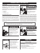
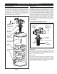
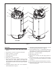
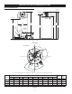
Table Of Contents
- Safe Installation, Use and Service
- APPROVALS
- General Safety Information
- Introduction
- Features And Components
- Installation Considerations
- Installation Requirements
- Gas Supply Systems
- Supply Gas Regulator
- Power Supply
- Mixing Valves
- Dishwashing Machines
- Closed Water Systems
- Thermal Expansion
- Temperature-Pressure Relief Valve
- Condensate Drain
- Combustible Material Storage
- Contaminated Air
- Air Requirements
- Unconfined Space
- Confined Space
- Fresh Air Openings For Confined Spaces
- Outdoor Air Through Two Openings
- Outdoor Air Through One Opening
- Outdoor Air Through Two Horizontal Ducts
- Outdoor Air Through Two Vertical Ducts
- Air From Other Indoor Spaces
- Installation Requirements - Commonwealth of Massachusetts
- Venting Installation
- General Venting Information
- General Venting Instructions
- Intake Air Connection
- Venting Requirements
- Venting Installation Sequence
- Power Vent Installation
- Direct Vent Installation
- Vertical Termination Installation
- Sidewall Termination Installation
- Polypropylene Installations
- Al29-4C® Vent Installations
- Concentric Termination Installation
- 4 Inch Concentric Termination Installation
- Low Profile Vent installation
- Venting Arrangements
- Termination Clearances Sidewall Power Vent
- Termination Clearances Sidewall Direct Vent
- Water Heater Installation
- Temperature Regulation
- Control System Operation
- Start Up
- Troubleshooting
- Maintenance
- Diagrams
- notes
- notes
- notes
- Service Inquiries:
- Commercial
- Water Heater
- Limited Warranty

9
9. Temperature-Pressure Relief Valve discharge pipe - see T&P
Valve Discharge Pipe Requirements: on page 15.
10. Lower Temperature Probe, 1 of 2 temperature probes. The
water heater’s control system monitors this probe to detect
water temperature in the lower portion of the storage tank.
11. Water inlet - 1 1/2” NPT connection.
12. Water heater drain valve.
13. Supply gas line connection. See Gas Supply Systems on
page 13.
14. Low Gas Pressure switch, see description under beginning
on page 8. See Gas Pressure Requirements and Table
3 on page 11.
15. Vent Connection (Exhaust/Condensate Elbow) 3" Aluminum.
16. Spark Ignition Control. When energized, sends the electrical
current to the spark igniter.
SIDE VIEWS
1. Cleanout access panel, covers water heater cleanout
opening.
2. CCB enclosure - see item 3 on page 8 for description.
3. Intake air connection - 3 inch PVC.
4. Water heater 24 Volt Gas Valve.
5. Combustion Blower.
6. Water outlet - 1 1/2” NPT connection.
7. UIM (user interface module). The UIM includes the display
circuit board, the control system’s LCD display and
operational buttons. Used to adjust various user settings and
view operational information. See Control System Operation
on page 45.
8. Temperature-Pressure Relief Valve. See Temperature-
Pressure Relief Valve on page 15.
LEFT SIDE RIGHT SIDE
1
1
10
12
11
15
15
8
3
3
14
4
13
5
6
7
4
16
2
2
9
5
Figure 4