
Install Instructions
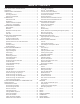
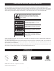
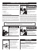
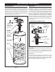
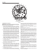
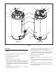
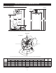
Table Of Contents
- Safe Installation, Use and Service
- APPROVALS
- General Safety Information
- Introduction
- Features And Components
- Installation Considerations
- Installation Requirements
- Gas Supply Systems
- Supply Gas Regulator
- Power Supply
- Mixing Valves
- Dishwashing Machines
- Closed Water Systems
- Thermal Expansion
- Temperature-Pressure Relief Valve
- Condensate Drain
- Combustible Material Storage
- Contaminated Air
- Air Requirements
- Unconfined Space
- Confined Space
- Fresh Air Openings For Confined Spaces
- Outdoor Air Through Two Openings
- Outdoor Air Through One Opening
- Outdoor Air Through Two Horizontal Ducts
- Outdoor Air Through Two Vertical Ducts
- Air From Other Indoor Spaces
- Installation Requirements - Commonwealth of Massachusetts
- Venting Installation
- General Venting Information
- General Venting Instructions
- Intake Air Connection
- Venting Requirements
- Venting Installation Sequence
- Power Vent Installation
- Direct Vent Installation
- Vertical Termination Installation
- Sidewall Termination Installation
- Polypropylene Installations
- Al29-4C® Vent Installations
- Concentric Termination Installation
- 4 Inch Concentric Termination Installation
- Low Profile Vent installation
- Venting Arrangements
- Termination Clearances Sidewall Power Vent
- Termination Clearances Sidewall Direct Vent
- Water Heater Installation
- Temperature Regulation
- Control System Operation
- Start Up
- Troubleshooting
- Maintenance
- Diagrams
- notes
- notes
- notes
- Service Inquiries:
- Commercial
- Water Heater
- Limited Warranty

10
ROUGH IN DIMENSIONS
INSTALLATION CONSIDERATIONS
MODEL
DIMENSIONS
SHIP
WEIGHT
STD
SHIP
WEIGHT
ASME
A B C D E F G H I J
INCHES/CM INCHES/CM INCHES/CM INCHES/CM INCHES/CM INCHES/CM INCHES/CM INCHES/CM INCHES/CM INCHES/CM LBS/KG LBS/KG
BTH 120
3/7.62 27.75/70.5 6.3/16 35/88.9 55.5/141 53.5/135.9 11.25/28.6 42.25/107.32 48.5/123.2 18.25/46.36 460/208 490/220
BTH 150
3/7.62 27.75/70.5 6.3/16 56.38/143.2 76/193.04 75.75/192.4 11.25/28.6 64/162.6 70/177.8 18.25/46.36 523/237 553/251
BTH 199
3/7.62 27.75/70.5 6.3/16 56.38/143.2 76/193.04 75.75/192.4 11.25/28.6 64/162.6 70/177.8 18.25/46.36 523/237 553/251
BTH 250
3/7.62 27.75/70.5 6.3/16 56.38/143.2 76/193.04 75.75/192.4 11.25/28.6 64/162.6 70/177.8 18.25/46.36 523/237 553/251
Figure 5
These designs comply with the current edition of the American National Standard for Gas Water Heaters, Volume III, ANSI Z21.10.3 / CSA 4.3
as an automatic circulating tank water heater, and automatic storage water heaters.
ALL MODELS
* Center line of water outlet on top of the water heaters is approximately 7 inches from the front edge of the water heater.
TOP VIEW
FRONT
BACK
VENT
CONNECTION
3 INCH PVC
(exhaust elbow)
E E
T & P VALVE
D
G
J
SUPPLY GAS
CONNECTION
F
B
CLEANOUT
3/4” NPT
DRAIN
3/4” NPT
RECIRCULATION
RETURN
1 1/2” NPT
WATER
INLET
LOWER
TEMPERATURE
PROBE
INTAKE AIR
CONNECTION
3 INCH PVC
H
I
WATER
OUTLET
HEIGHT
C
A
45°
30°
GAS
CLEAN OUT
T&P VALVE
DRAIN
VALVE
FRONT
1½" NPT WATER
OUTLET
EXHAUST
AIR INTAKE
18°
42°
26°
90°