Instruction Manual RESIDENTIAL GAS WATER HEATERS DIRECT VENT GAS MODELS GDV/GDVT NOT FOR USE IN MANUFACTURED (MOBILE) HOMES 500 Tennessee Waltz Parkway Ashland City, TN 37015 • For Your Safety • AN ODORANT IS ADDED TO THE GAS USED BY THIS WATER HEATER. ALL TECHNICAL AND WARRANTY QUESTIONS: SHOULD BE DIRECTED TO THE LOCAL DEALER FROM WHOM THE WATER HEATER WAS PURCHASED. IF YOU ARE UNSUCCESSFUL, PLEASE WRITE TO THE COMPANY LISTED ON THE RATING PLATE ON THE WATER HEATER.
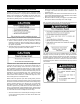
SAFE INSTALLATION, USE AND SERVICE Your safety and the safety of others is extremely important in the installation, use and servicing of this water heater. Many safety-related messages and instructions have been provided in this manual and on your own water heater to warn you and others of a potential injury hazard. Read and obey all safety messages and instructions throughout this manual.
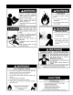
GENERAL SAFETY 3
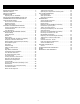
TABLE OF CONTENTS SAFE INSTALLATION, USE AND SERVICE 2 IMPORTANT DEFINITIONS. . . . . . . . . . . . . . . . . . . . . . . . . . . 2 GENERAL SAFETY 3 TABLE OF CONTENTS 4 INTRODUCTION 5 Preparing For The Installation . . . . . . . . . . . . . . . . . . . . . . 5 INSTALLATION REQUIREMENTS FOR THE COMMONWEALTH OF MASSACHUSETTS 6 TYPICAL INSTALLATION 7 Get To Know Your Water Heater. . . . . . . . . . . . . . . . . . . . . 7 Replacement Parts . . . . . . . . . . . . . . . . . . . . . . . . . . . . . . .
INTRODUCTION Thank You for purchasing this water heater. Properly installed and maintained, it should give you years of trouble free service.
INSTALLATION REQUIREMENTS FOR THE COMMONWEALTH OF MASSACHUSETTS For all side wall terminated, horizontally vented power vent, direct vent, and power direct vent gas fueled water heaters installed in every dwelling, building or structure used in whole or in part for residential purposes, including those owned or operated by the Commonwealth and where the side wall exhaust vent termination is less than seven (7) feet above finished grade in the area of the venting, including but not limited to decks and porch
TYPICAL INSTALLATION GET TO KNOW YOUR WATER HEATER REPLACEMENT PARTS Replacement parts may be ordered through authorized servicers or distributors. When ordering parts, provide complete model and serial numbers (see rating plate), quantity and name of part desired (as listed in Figure 1). Standard hardware items may be purchased locally.
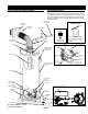
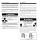
MIXING VALVE USAGE TEMPERED POTABLE WATER MIXING VALVE SHUT-OFF VALVE COLD WATER INLET NON-TEMPERED WATER SUPPLY NON-TEMPERED WATER RETURN SUGGESTED PIPING ARRANGEMENT FOR TOP CONNECTIONS TEMPERATURE-PRESSURE RELIEF VALVE GAS SUPPLY DISCHARGE PIPE (DO NOT CAP OR PLUG) CERTAIN MODELS ARE EQUIPPED WITH SIDE PLUMBING CONNECTIONS FOR SPACE HEATING.
LOCATING THE NEW WATER HEATER • FACTS TO CONSIDER ABOUT THE LOCATION Carefully choose an indoor location for the new water heater, because the placement is a very important consideration for the safety of the occupants in the building and for the most economical use of the appliance. This water heater is not for use in manufactured (mobile) homes or outdoor installation.
INSULATION BLANKETS VENT TERMINATION Insulation blankets available to the general public for external use on gas water heaters are not necessary with this product. The purpose of an insulation blanket is to reduce the standby heat loss encountered with storage tank water heaters. Your Water heater meets or exceeds the National Appliance Energy Conservation Act standards with respect to insulation and standby loss requirements, making an insulation blanket unnecessary.
INSTALLING THE NEW WATER HEATER REQUIRED ABILITY INSTALLATION OR SERVICE OF THIS WATER HEATER REQUIRES ABILITY EQUIVALENT TO THAT OF A LICENSED TRADESMAN IN THE FIELD INVOLVED. PLUMBING, AIR SUPPLY, VENTING AND GAS SUPPLY ARE REQUIRED. INSPECT SHIPMENT This water heater shall not be connected to any heating systems or component(s) used with a non-potable water heating appliance. There may be hidden damage caused in transit. Check to be certain all parts of the venting system, as listed below, are present.
4. Locate the hot water (outlet) & cold water (inlet) pipes to the water heater. 5. Locate the slit running the length of a section of pipe insulation. 6. Spread the slit open and slip the insulation over the cold water (inlet) pipe. Apply gentle pressure along the length of the insulation to ensure that it is fully seated around the pipe. Also, ensure that the base of the insulation is flush with the water heater. Once seated, secure the insulation with duct tape, electrical tape, or equivalent. 7.
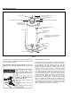
The temperature-pressure relief valve must be installed directly into the fitting of the water heater designed for the relief valve. Position the valve downward and provide tubing so that any discharge will exit only within 6 in. above, or at any distance below the structural floor. Be certain that no contact is made with any live electrical part. The discharge opening must not be blocked or reduced in size under any circumstances. Excessive length, over 30 ft.
GAS PIPING Make sure the gas supplied is the same type listed on the model rating plate. The inlet gas pressure must not exceed 14 inch water column (3.5 kPa) for natural and propane gas (L.P.). The minimum inlet gas pressure shown on the rating plate is that which will permit firing at rated input.
Gas piping with flexible connector. HOT WATER OUTLET COLD WATER INTLET SHUTOFF VALVE UNION UNION TEMPERATURE AND PRESSURE RELIEF VALVE FIGURE 7 Gas piping with all black iron pipe to gas control. DISCHARGE PIPE (DO NOT CAP OR PLUG) METAL DRAIN PAN FIGURE 8 SEDIMENT TRAPS DRAIN VALVE 6” MAXIMUM AIR GAP FLOOR DRAIN FIGURE 9 FILLING THE WATER HEATER A sediment trap (dirt leg) shall be installed as close to the inlet of the water heater as practical at the time of water heater installation.
VENTILATING AIR. ADEQUATE AIR FOR COMBUSTION AND VENTILATION MUST BE PROVIDED FOR SAFE OPERATION. HIGH ALTITUDE INSTALLATIONS Installations above 7,700 ft. require replacement of the burner orifice in accordance with the current edition of the National Fuel Gas Code ANSI Z223.1/NFPA 54. Failure to replace the orifice could result in improper and inefficient operation of the appliance, producing carbon monoxide gas in excess of safe limits, which could result in serious personal injury or death.
VENT CONNECTIONS 7 in. DIAMETER After the location for the vent terminal has been selected as outlined in Figures 3 & 15, use the following illustrations for installation: (SEE TEXT) BOTTOM OF HEATER FIGURE 13 HIGH RISE VENT ARRANGEMENT When the height H (From vent terminal center line to bottom of heater) is over 80 in. , it is a high rise vent arrangement. In this case the minimum distance “D” from the center of the water heater to the outside wall surface is 22 in.
STANDARD VENT ARRANGEMENT 3.6 in. 17 in. MIN.,* 80 in. MAX. 2.6 in. UNCOMPRESSING THE CORRUGATED TUBING 1. Pull the inner corrugated tube towards the water heater and leave some length over the water heater’s center for bending. 2. Pull the outer corrugated tube toward the water heater and leave it 1 in. shorter than the inner corrugated tube. 3. Make sure there are two springs evenly spaced at the bend in the tube. 4.
OFFSET VENT ARRANGEMENT CONDITION 1: Where a straight vent arrangement is impossible, a horizontal 90 degree maximum bend can be made. Use the water heater casing outer diameter as a template to form the corrugated tube. TOP VIEW 90° MAXIMUM BEND FIGURE 22 Apply hi-temp red silicone (included) around the collar on air manifold box. Pull corrugated vent tube all the way on to collar and secure with one sheet metal screw (approx. 3/4 in. up from edge of vent tube. Pull gear clamp past screw and tighten.
FOR YOUR SAFETY READ BEFORE LIGHTING WARNING: If you do not follow these instructions exactly, a fire WARNING: If you do not follow these instructions exactly, a fire oror explosion may result causing property damage, personalpersonal injury orinjury loss oforlife. explosion may result causing property damage, loss of life. FLAMMABLE BEFORE LIGHTING: ENTIRE SYSTEM MUST BE FILLED WITH WATER AND AIR PURGED FROM ALL LINES A.
TEMPERATURE REGULATION TEMPERATURE REGULATION GAS CONTROL VALVE/THERMOSTAT SETTINGS GAS CONTROL/ TEMPERATURE KNOB STATUS LIGHT 130°F 140°F 150°F 155°F MARK MARK MARK MARK 120°F MARK 91°F MARK IGNITER FIGURE 26 Should overheating occur or the gas supply fail to shut off, turn off the manual gas control valve to the appliance. NOTE: During low demand periods when hot water is not being used, a lower thermostat setting will reduce energy losses and may satisfy your normal hot water needs.
FOR YOUR INFORMATION THERMAL EXPANSION EXTERNAL DAMAGE Do not operate the water heater until it has been fully checked out by a qualified technician, if the water heater: • • • Has been exposed to fire or damage. Displays evidence of sooting. Produces steam or unusually hot water. If the water heater has been flooded it must be replaced.
OPERATIONAL CONDITIONS SMELLY WATER In each water heater there is installed at least one anode rod (see parts section) for corrosion protection of the tank. Certain water conditions will cause a reaction between this rod and the water. The most common complaint associated with the anode rod is one of a “rotten egg smell” in the hot water. The smell is a result of four factors which must all be present for the odor to develop: a. A concentration of sulfate in the supply water. b.
MAINTENANCE a flooded water heater. Do not attempt to repair the unit! It must be replaced! At least once a year a visual inspection should be made of the main burner and the pilot assembly for proper flame characteristics. This can be done by removing the Outer Door and viewing the main burner operation through the Viewport on the Inner Door, see Figure 1.
SOOT BUILD-UP INDICATES A PROBLEM THAT REQUIRES CORRECTION BEFORE FURTHER USE. CONSULT WITH A QUALIFIED SERVICE TECHNICIAN. Should the main burner or burner air openings require cleaning, turn the gas control knob to “OFF” position and allow the burner to cool. Remove the burner and clean with a soft brush. Clean main burner orifice with a suitable soft material. REPLACING THE MANIFOLD/BURNER ASSEMBLY WARNING Explosion Hazard Tighten both manifold door screws securely.
2. Turn off the gas at the manual shut-off valve on the gas supply pipe (Figure 3). 3. Drain the water heater. Refer to the section of “Draining and Flushing” and follow the procedure. 4. Disconnect the igniter wire from the igniter lead wire. Use needle nose pliers to disconnect the red (+) and white (-) thermopile wires. Disconnect the pilot tube (7/16” wrench) and manifold tube (3/4” wrench) at the gas control valve/thermostat (Figure 22). NOTE: L.P.
REMOVING THE BURNER FROM THE MANIFOLD/ BURNER ASSEMBLY THERMOPILE CONNECTOR NATURAL GAS (LOW NOX) & L.P. GAS BURNER 1. Take off the burner by removing the two (2) screws located underneath the burner. 2. Check the burner to see if it is dirty or clogged. The burner may be cleaned with soap and hot water (Figure 24).Important: DO NOT remove the orifice.
TEMPERATURE & PRESSURE RELIEF VALVE CATHODIC PROTECTION - ANODE At least once a year, the temperature and pressure relief valve, Figure 1, must be checked to ensure that it is in operating condition. Lift the lever at the top of the valve several times until the valve seats properly and operates freely. If water does not flow, remove the valve and inspect for obstructions or corrosion. Have a qualified service agent replace with a new valve of the recommended size as necessary.
To replace the anode: 1. Turn off gas supply to the water heater. 2. Shut off the water supply and open a nearby hot water faucet to depressurize the water tank. 3. Drain approximately 5 gallons of water from tank. (Refer to “Draining and Flushing” for proper procedures). Close drain valve. 4. Remove old anode rod. 5. Use Teflon® tape or approved pipe sealant on threads and install new anode rod. 6. Turn on water supply and open a nearby hot water faucet to purge air from water system.
LEAKAGE CHECKPOINTS SERVICE A If a condition persists or you are uncertain about the operation of the water heater contact a service agency. Use this guide to check a “Leaking” water heater. Many suspected “Leakers” are not leaking tanks. Often the source of the water can be found and corrected. B B C If you are not thoroughly familiar with gas codes, your water heater, and safety practices, contact your gas supplier or qualified installer to check the water heater. E Read this manual first.
TROUBLESHOOTING GUIDELINES PROBLEM BURNER WILL NOT IGNITE SMELLY WATER BURNER FLAME YELLOWLAZY PILOT WILL NOT LIGHT OR REMAIN LIT HIGH OPERATION COSTS PILOT FLAME TOO SMALL INSUFFICIENT HOT WATER SLOW HOT WATER RECOVERY POSSIBLE CAUSE(S) 1. 2. 3. 4. 5. 6. 7. 8. Pilot not lit Thermostat set too low No gas Dirt in the gas lines Pilot line clogged Main burner line clogged Defective thermopile Defective gas control/thermostat CORRECTION 1. 2. 3. 4. 5. 6. 7. 8. Light pilot Turn temp.
PROBLEM DRIP FROM RELIEF VALVE THERMOSTAT FAILS TO SHUT OFF COMBUSTION ODORS SMOKING AND CARBON FORMATION (SOOTING) CONDENSATION BURNER FLAME FLOATS AND LIFTS OFF PORTS POSSIBLE CAUSE(S) 1. 2. 3. 4. Excessive water pressure Heater stacking Closed water system Temperature setting too high CORRECTION 1. Use a pressure reducing valve and relief valve 2. Lower the thermostat setting 3. See “Closed System/Thermal Expansion” 4. Decrease the temperature setting 1. Defective gas control/thermostat 2.
NOTES 33
RESIDENTIAL GAS WARRANTY This warranty shall apply only when the heater is: • owned by the original purchaser; • installed for indoor operation only; • used at temperatures not exceeding the maximum calibrated setting of its thermostat; • used at water pressure not exceeding the working pressure shown on the heater; • filled with potable water, free to circulate at all times and with the tank free of damaging water sediment or scale deposits; • used in a non-corrosive and non-contaminated atmosphere; • used
SERVICE AND LABOR RESPONSIBILITY PROOF-OF-PURCHASE AND PROOF-OF-INSTALLATION DATE ARE REQUIRED TO SUPPORT WARRANTY CLAIM FROM ORIGINAL OWNER. THIS FORM DOES NOT CONSTITUTE PROOF-OF-PURCHASE OR PROOF-OFINSTALLATION. DISCLAIMERS UNDER THIS LIMITED WARRANTY, THE WARRANTOR WILL PROVIDE ONLY A REPLACEMENT WATER HEATER OR PART THEREOF. THE OWNER IS RESPONSIBLE FOR ALL OTHER COSTS.
500 TENNESSEE WALTZ PARKWAY ASHLAND CITY, TN 37015 PHONE: 1-800-433-2545 FAX: 1-800-433-2515 www.aosmithwaterheaters.com / email: parts@hotwater.