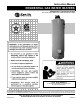
Instruction Manual RESIDENTIAL GAS WATER HEATERS POWER DIRECT VENTED GAS MODELS NOT FOR USE IN MANUFACTURED (MOBILE) HOMES LOW LEAD CONTENT • For Your Safety • AN ODORANT IS ADDED TO THE GAS USED BY THIS WATER HEATER. ALL TECHNICAL AND WARRANTY QUESTIONS: SHOULD BE DIRECTED TO THE LOCAL DEALER FROM WHOM THE WATER HEATER WAS PURCHASED. IF YOU ARE UNSUCCESSFUL, PLEASE WRITE TO THE COMPANY LISTED ON THE RATING PLATE ON THE WATER HEATER.
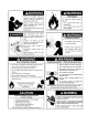
SAFE INSTALLATION, USE, AND SERVICE Your safety and the safety of others is extremely important in the installation, use, and servicing of this water heater. Many safety-related messages and instructions have been provided in this manual and on your own water heater to warn you and others of a potential hazard. Read and obey all safety messages and instructions throughout this manual.
TABLE OF CONTENTS Cutting Openings Through an Outside Wall and Collar Installation ....................................................... 19 Installation Showing Use of PVC, ABS or CPVC Pipe for Inlet and Outlet Vent Piping ................................................. 19 Connecting Vent to Blower ........................................................... 20 Installation Showing Use of (optional) Concentric Termination Kit ........................................................
INSTALLATION REQUIREMENTS FOR THE COMMONWEALTH OF MASSACHUSETTS For all side wall terminated, horizontally vented power vent, direct vent, and power direct vent gas fueled water heaters installed in every dwelling, building or structure used in whole or in part for residential purposes, including those owned or operated by the Commonwealth and where the side wall exhaust vent termination is less than seven (7) feet above finished grade in the area of the venting, including but not limited to decks and porch
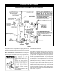
TYPICAL INSTALLATION GET TO KNOW YOUR WATER HEATER - GAS MODELS A B C D E F G H I Vent Pipe–Exhaust Vent Terminal–Exhaust Intake or Combustion Air Pipe Intake or Combustion Air Terminal Vent Adapter Blower Assembly Cold Water Inlet Inlet Water Shut-off Valve Union J K L M N O P Q R S T U V W X Y Z AA BB CC Inlet Dip Tube Anode** Hot Water Outlet Outlet Receptacle (115 VAC) Temperature-Pressure Relief Valve Flue Flue Baffle Assembly** Insulation Rating Plate Gas Supply Manual Gas Shut-off Valve Ground J
MIXING VALVE USAGE SUGGESTED PIPING ARRANGEMENT FOR TOP CONNECTIONS FIGURE 2. This appliance has been design certified as complying with American National Standard/CSA Standard for water heaters and is considered suitable for: HOTTER WATER CAN SCALD: Water heaters are intended to produce hot water. Water heated to a temperature which will satisfy space heating, clothes washing, dish washing, and other sanitizing needs can scald and permanently injure you upon contact.
LOCATING THE NEW WATER HEATER FACTS TO CONSIDER ABOUT THE LOCATION water heater’s hot surface igniter or main burner. The resulting flashback and fire can cause death, serious burns to anyone in the area or property damage. This water heater is equipped with an FV sensor for detecting the presence of flammable vapors. See Figure 3. When the sensor detects those vapors, the unit will shut down and not operate. Should this happen, please refer to the troubleshooting guide in this manual.
FIGURE 5. Minimum clearances between the water heater and combustible construction are 0 inch at the sides and rear, 6” (15.2 cm) from the front of the jacket, and 12” (30.5 cm) from the top (standard clearance). If clearances stated on the heater differ from standard clearances, install water heater according to clearances stated on the heater.
VENT TERMINATION CLEARANCES ......... FIGURE 7. WIRE FENCE • The vent exhaust outlet and air inlet terminals shall terminate at least 18" (45.7 cm) above the roof surface, see Figure 9. When the water heater outlet terminal is low enough to be touched accidentally, or is accessible to small children, a wire mesh chain link fence (as shown in Figure 8) may be used. Care should be taken to maintain adequate ventilation around the outlet terminal.
Should you choose to apply an insulation blanket to this heater, you should follow these instructions. (For identification of the components mentioned in the next column, see Figure 1.) Failure to follow these instructions can restrict the air flow required for proper combustion, potentially resulting in fire, asphyxiation, serious personal injury, or death. • Do not apply insulation to the top of the water heater, as this will interfere with safe operation of the water heater.
INSTALLING THE NEW WATER HEATER WATER PIPING THERMAL EXPANSION As water is heated, it expands (thermal expansion). In a closed system the volume of water will grow. As the volume of water grows there will be a corresponding increase in water pressure due to thermal expansion. Thermal expansion can cause premature tank failure (leakage). This type of failure is not covered under the limited warranty.
If replaced, the valve must meet the requirements of local codes, but not less than a combination temperature and pressure relief valve certified as indicated in the above paragraph. solder the cold water supply line directly to the cold water inlet. It will harm the dip tube and damage the tank.
line, and (2) the water manually discharged will not cause any bodily injury or property damage because the water may be extremely hot. If after manually operating the valve, it fails to completely reset and continues to release water, immediately close the cold water inlet to the water heater, follow the draining instructions, and replace the temperature-pressure relief valve with a new one.
. FIGURE 12. GAS PIPING WITH FLEXIBLE CONNECTOR. . FIGURE 14. FIGURE 13. GAS PIPING WITH ALL BLACK IRON PIPE TO GAS CONTROL. FILLING THE WATER HEATER SEDIMENT TRAPS . Never use this water heater unless it is completely full of water. To prevent damage to the tank, the tank must be filled with water. Water must flow from the hot water faucet before turning “ON” gas to the water heater. To fill the water heater with water: 1.
WIRING SCHEMATIC DIAGRAM 1. or outlet providing power to this water heater must be wired properly (correct polarity). 8. Do not plug in power cord until vent system is completely installed. This power direct vent heater operates on 110-120 Vac, therefore a grounded outlet must be within reach of the six (6) foot (1.8 m) flexible power cord supplied with the unit. See Figure 2. The power cord supplied may be used only where local codes permit.
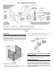
VENT CONNECTIONS TO BLOWER ASSEMBLY Figure 15 shows the typical vent connections. FIGURE 16. Horizontal runs must be securely supported at 3 1/2 foot (1 m) intervals and vertical runs supported at 5 foot (1.5 m) intervals. FIGURE 15. VENTING AND INSTALLATION Plan the layout of the vent system from the vent termination to the water heater considering all of the 90° and 45° elbows plus the number of feet of pipe that would be needed to install the total vent system.
VENTING SYSTEM EXAMPLE INSTALLATIONS FOR ALL MODELS 4. The unit cannot be connected to existing vent piping or chimney. 5. When venting through an outside wall, the vents must terminate horizontally to the outdoors. Do not run the vent piping downward under any circumstances. See Figure 21. B. All 50 Gallon 65,000 BTU/HR Models In the carton is supplied: 1. Two 3” inlet and outlet PVC Schedule 40 - 45° vent caps. 2.
FIGURE 23B. 3. Minimum vent length for all models is 18 inches (46 cm). VENT PIPE SEPARATION FIGURE 25. The inlet and outlet vent pipes must be separated by a minimum distance of 6 1/2 inches (16.5 cm) up to 24 inches (61 cm) maximum. The 3” PVC, ABS, or CPVC Schedule 40 vent pipe can be run from the water heater through the wall or from the wall to the water heater, whichever is most convenient. The vent pipe must extend a minimum of 1 1/2” (4 cm) through the exterior wall.
CONNECTING VENT TO BLOWER VENTING THROUGH A ROOF 1. If making an immediate horizontal run of vent off the blower, install the following at the blower inlet: one 3" PVC Schedule 40 pipe (3" long minimum) and one 3" PVC Schedule 40 elbow. At the outlet, install one 3" PVC Schedule 40 street elbow. (Exception: For the outlet, use CPVC for 75 gallon models and ABS for 50 gallon 65,000 Btu/Hr models.) Place the elbows in the required direction on the blower, then secure as described in Figure 27.
PRIMER FIGURE 30. It is recommended that Tetrahydrofuran (THF) be used to prepare the surfaces of pipe and fittings for solvent welding. Do not use water, rags, gasoline or any other substitutes for cleaning PVC, ABS or CPVC surfaces. A chemical cleaner such as MEK may be used. VENT PIPE PREPARATION 1. INITIAL PREPARATION A. CEMENT Make sure the solvent cement you are planning to use is designed for the specific application you are attempting. B.
3. MAKING THE JOINT Apply primer to the surface of the pipe and fitting socket with a natural bristle brush. This process softens and prepares the PVC, ABS or CPVC for the solvent cementing step. Move quickly and without hesitation to the cementing procedure while the surfaces are still wet with primer. A. Cutting Pipe must be squarely cut to allow for the proper interfacing of the pipe end and the fitting socket bottom. This can be accomplished with a miter box saw or wheel type cutter.
TEMPERATURE REGULATION Due to the nature of the typical gas water heater, the water temperature in certain situations may vary up to 30°F (16.7°C) higher or lower at the point of use such as, bathtubs, showers, sink, etc. To avoid any unintentional changes in water temperature settings, the gas control valve/thermostat has a tamper resistant feature for changing the temperature setting.
FOR YOUR INFORMATION START UP CONDITIONS to thermal expansion. Thermal expansion can cause premature tank failure (leakage). This type of failure is not covered under the limited warranty. Thermal expansion can also cause intermittent temperature-pressure relief valve operation: water discharged from the valve due to excessive pressure build up. The temperaturepressure relief valve is not intended for the constant relief of thermal expansion. This condition is not covered under the limited warranty.
PERIODIC MAINTENANCE characteristics and ignition sequences. This can be done by viewing the main burner operation through the Viewport on the Outer Door, see Figure 1. The main burner should provide complete combustion of gas, ignite rapidly, give reasonably quiet operation, and cause no excessive flame lifting from the burner ports. If the proper flame characteristics are not evident as in Figure 32, make sure that the flow of combustion and ventilation air is not blocked in the venting system.
ANODE ROD In replacing the anode: 1. Turn off gas supply to the water heater. 2. Shut off the water supply and open a nearby hot water faucet to depressurize the water tank. 3. Drain approximately 5 gallons (18.9 L) of water from the tank (Refer to the "Draining and Flushing" section for proper procedures). Close drain valve. 4. Remove old anode rod. 5. Use Teflon® tape or approved pipe sealant on threads and install new anode rod. 6.
DRAIN VALVE WASHER REPLACEMENT You may have a check valve installed in the water line or a water meter with a check valve. Consult your local water supplier or service agency for further information. Do not plug the temperature-pressure relief valve. (See Figure 34) 1. Turn “OFF” gas supply to water heater. 2. Follow “Draining” instructions. DRAINING AND FLUSHING 3. Turning counterclockwise ( screw handle. ), remove the hex cap below the 4. Remove the washer and put the new one in place. 5.
LEAKAGE CHECKPOINTS Read this manual first. Then before checking the water heater make sure the gas supply has been turned “OFF”, and never turn the gas “ON” before the tank is completely full of water. Never use this water heater unless it is completely filled with water. To prevent damage to the tank, the tank must be filled with water. Water must flow from the hot water faucet before turning “ON” gas to the water heater. A.
REPAIR PARTS LIST Key No. Part Description 1 Vent Cap w/Screen 2 Adaptor, Flue Mounting 3 5' ABS Schedule 40 Vent Pipe (50 gal. 65,000) 3 5' CPVC Schedule 40 Vent Pipe (75 gal.) 4 90° ABS Schedule 40 Elbow (50 gal. 65,000) 4 90° CPVC Schedule 80 Elbow (75 gal.) 5 Vent/Blower Adapter 6 Blower 7 Flue Adaptor Gasket (6' x 10.
TROUBLESHOOTING GUIDELINES TROUBLE SHOOTING Please check guidelines below. For your safety, water heater service should be performed only by a qualified service technician. Read the GENERAL SAFETY INFORMATION section first. # 1 LED STATUS PROBLEM SOLUTION The gas control valve/thermostat has sensed inadequate or no earth ground. 1 Ensure the wall outlet (power supply) is properly grounded. 2 Ensure all ground connections/wires on the water heater are securely connected.
# 7 8 9 10 11 12 13 14 LED STATUS PROBLEM SOLUTION Self diagnostic check has detected a problem with the gas valve driver circuit, internal microprocessor, or other internal circuits. The gas control valve/thermostat has sensed main burner flame out of proper sequence. Water temperature in the tank has exceeded 195° F and has activated the ECO (energy cut off) high temperature limit. Self diagnostic check has detected that one or both of the temperature adjust buttons are stuck.
TROUBLESHOOTING GUIDELINES These guidelines should be utilized by a qualified service agent. When calling for service notify the service agent that this is a “Flammable Vapor Ignition Resistant” Product. PROBLEM CAUSE SOLUTION 1. Blower will not run. NOT ENOUGH OR NO HOT WATER A) "ON/OFF" control switch turned off. Turn switch to the "ON" position. B) Blower unplugged. Plug blower back into 115 vac. outlet. C) No power at outlet. Repair service to outlet. D) Thermostat defective.
RESIDENTIAL GAS LIMITED WARRANTY THIS WARRANTY IS APPLICABLE TO THE ORIGINAL OWNER ONLY, in accordance with the warranty terms and conditions specified below. • • • A. O. Smith Water Heaters (the warrantor) will furnish the ORIGINAL OWNER, 1) a replacement A. O. Smith water heater of equivalent size and current model if the glass-lined tank in this water heater leaks and, 2) a replacement part for any component part which fails. • • • THE A. O.
PROOF-OF-PURCHASE AND PROOF-OF-INSTALLATION DATE ARE REQUIRED TO SUPPORT WARRANTY CLAIM UNDER THIS LIMITED WARRANTY, THE WARRANTOR FROM ORIGINAL OWNER. THIS FORM DOES NOT WILL PROVIDE ONLY A REPLACEMENT WATER HEATER CONSTITUTE PROOF-OF-PURCHASE OR PROOF-OFOR PART THEREOF. THE OWNER IS RESPONSIBLE FOR INSTALLATION. ALL OTHER COSTS. Such costs may include but are not DISCLAIMERS limited to: SERVICE AND LABOR RESPONSIBILITY a.
Copyright © 2012 A.O. Smith Corporation. All rights reserved.