Installation and Operating Manual RESIDENTIAL GAS WATER HEATERS POWER VENTED GAS MODELS WITH HOT SURFACE IGNITION NOT FOR USE IN MANUFACTURED (MOBILE) HOMES • For Your Safety • AN ODORANT IS ADDED TO THE GAS USED BY THIS WATER HEATER. ALL TECHNICAL AND WARRANTY QUESTIONS: SHOULD BE DIRECTED TO THE LOCAL DEALER FROM WHOM THE WATER HEATER WAS PURCHASED. IF YOU ARE UNSUCCESSFUL, PLEASE CONTACT THE COMPANY LISTED ON THE RATING PLATE ON THE WATER HEATER.
TABLE OF CONTENTS TABLE OF CONTENTS SAFE INSTALLATION, USE AND SERVICE GENERAL SAFETY INTRODUCTION 2 3 4 6 Qualified Installer Or Service Agency . . . . . . . . . . . . 6 Preparing For The Installation . . . . . . . . . . . . . . . . . . 6 INSTALLATION REQUIREMENTS FOR THE COMMONWEALTH OF MASSACHUSETTS TYPICAL INSTALLATION 7 9 Get To Know Your Water Heater - Gas Models (List Referencing Figures 1-7). . . . . . . . . . . . . . . . . . 9 Replacement Parts And Deliming Products . . . . . .
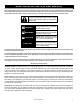
SAFE INSTALLATION, USE AND SERVICE Your safety and the safety of others is extremely important in the installation, use and servicing of this water heater. Many safety-related messages and instructions have been provided in this manual and on your own water heater to warn you and others of a potential injury hazard. Read and obey all safety messages and instructions throughout this manual.
GENERAL SAFETY 4 www.hotwater.
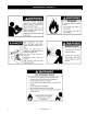
GENERAL SAFETY DANGER WARNING Breathing Hazard - Carbon Monoxide Gas • Install vent system in accordance with codes. • Do not operate water heater if flood damaged. • For operation above 10,100’ (3,079 m), a high altitude orifice must be installed. • Do not operate if soot buildup is present. • Do not obstruct water heater air intake with insulating jacket. FLAMMBLE Flammable Vapors • Do not obstruct blower air intake. • Do not place chemical vapor emitting products near water heater.
INTRODUCTION Thank You for purchasing this water heater. Properly installed and maintained, it should give you years of trouble free service. Abbreviations found in this Installation and Operating manual: • CSA - Canadian Standards Association • ANSI - American National Standards Institute • NFPA - National Fire Protection Association • ASME - American Society of Mechanical Engineers • GAMA - Gas Appliance Manufacturer’s Association • UL - Underwriters Laboratories Inc.
INSTALLATION REQUIREMENTS FOR THE COMMONWEALTH OF MASSACHUSETTS COMMONWEALTH OF MASSACHUSETTS For all side wall terminated, horizontally vented power vent, direct vent and power direct vent gas fueled water heaters installed in every dwelling, building or structure used in whole or in part for residential purposes, including those owned or operated by the Commonwealth and where the side wall exhaust vent termination is less than seven (7) feet above finished grade in the area of the venting, including but n
INSTALLATION GRAPHIC: GAS-FIRED POTABLE WATER HEATING/SPACE HEATING SYSTEM • If your water heater will be installed in the Commonwealth of Massachusetts, refer to the following graphic during installation and during modifications to the water supply system. TYPICAL MIXING VALVE INSTALLATION COMBINATION SPACE HEATING / POTABLE WATER HEATING SYSTEM EXPANSION TANK TEMPERED WATER TO FIXTURES (MUST MEET TEMPS LISTED IN MASS.
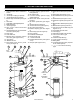
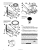
TYPICAL INSTALLATION GET TO KNOW YOUR WATER HEATER - GAS MODELS (list referencing Figures 1-7) 1. Vent Termination Elbow with Rodent Screen 2. *Vent Pipe 3. *Vent Pipe Coupling (if required) 4. *Vent Pipe Elbow (long radius) 5. Blower High Limit Switch (see Figure 6) 6. T&P Valve 7. Cold-Water Inlet Nipple/Diptube 8. Baffle Assembly 9. * Discharge Pipe 10. Gas Control Valve/Thermostat (Honeywell) 11. Gas Valve Electronic Control Module And Cover (Honeywell) 12. Drain Valve 13. Outer Gas Door 14.
Natural gas and Propane main burner with igniter assembly for 40k to 50k Btu/hr models 22 25 26 23 34 35 32 27 24 36 37 21 38 33 39 41 5 Figure 6 Vacuum relief valve install per local codes (not supplied with heater). 40 Figure 3 Natural gas and Propane main burner with igniter assembly for 60k to 75k Btu/hr models 32 Figure 7 34 35 36 37 38 33 39 41 Figure 4 40 Notes: * Items not supplied with the water heater.
WATER PIPING - MIXING VALVE USAGE Mixing Valves DANGER Water temperature over 125°F (52°C) can cause severe burns instantly resulting in severe injury or death. Children, the elderly and the disabled and are at highest risk of scald injury. Feel water before bathing or showering. HOT BURN Temperature limiting devices such as mixing must be installed when required by codes and to ensure safe temperatures at fixtures.
Some people are more likely to be permanently injured by hot water than others. These include the elderly, children, the infirm and the physically/mentally disabled. Table 1 (published by U.S. Government Memorandum, 1978) shows the approximate time-to-burn relationship for normal adult skin.
ELECTRICAL REQUIREMENTS & WIRING DIAGRAM WARNING Electric Shock Hazard Disconnect power before servicing. CAUTION LABEL ALL WIRES PRIOR TO DISCONNECTION WHEN SERVICING CONTROLS. WIRING ERRORS CAN CAUSE IMPROPER AND DANGEROUS OPERATION. VERIFY PROPER OPERATION AFTER SERVICING. POWER VENT WIRING SCHEMATIC. NOTE: REFER TO THE “INSTALLATION CHECKLIST” BEFORE OPERATING THIS HEATER. Replace all parts and panels before operating. Failure to do so can result in death or electrical shock.
SAFETY LOCKOUTS This water heater has several lockout features designed to prevent the heater from operating in unsafe conditions. HIGH LIMIT CONTROLS (TCO) Thermostat/Water Temperature This feature is a part of the gas control valve/thermostat (see Figure 1, item 10) and limits the maximum water temperature. In the event of the water overheating, this safety feature shuts off the fuel supply to the burner. If the high limit is tripped, it requires manual resetting (see “TCO Resettable Lockout”).
LOCATING THE NEW WATER HEATER FACTS TO CONSIDER ABOUT THE LOCATION Carefully choose an indoor location for the new water heater because the placement is a very important consideration for the safety of the occupants in the building and for the most economical use of the appliance. This water heater is not for use in manufactured (mobile) homes or outdoor installation. Whether replacing an old water heater or putting the water heater in a new location, the following critical points must be observed: 1.
Clearance for servicing Adequate clearance of 24” (61cm) for servicing this appliance should be considered before installation, such as changing the anodes, etc. WARNING Fire or Explosion Hazard • Do not store or use gasoline or other flammable vapors and liquids in the vicinity of this or any other appliance. • Avoid all ignition sources if you smell gas. • Do not expose water heater control to excessive gas pressure. • Use only gas shown on rating plate. • Maintain required clearances to combustibles.
If this water heater will be used in beauty shops, barber shops, cleaning establishments, or self-service laundries with dry cleaning equipment, it is imperative that the water heater or water heaters be installed so that combustion and ventilation air be taken from outside these areas. Propellants of aerosol sprays and volatile compounds, (cleaners, chlorine based chemicals, refrigerants, etc.
method used to provide fresh air to the confined space and the total Btu/hr input rating of all appliances installed in the space. DIRECT VENT APPLIANCES Other appliances installed in a Direct Vent configuration that derive all air for combustion from the outdoor atmosphere through sealed intake air piping are not factored in the total appliance input Btu/hr calculations used to determine the size of openings providing fresh air into confined spaces.
Figure 19 4. When ducts are used, they shall be of the same cross-sectional area as the free area of the openings to which they connect. The minimum short side dimension of rectangular air ducts shall not be less than 3” (76mm) (see Figure 20). Figure 20 5. Alternatively a single permanent opening may be used when communicating directly with the outdoors, or with spaces that freely communicate with the outdoors. The opening shall have a minimum free area of 1 square inch per 3,000 Btu/hr (8.
INSTALLING THE NEW WATER HEATER WATER PIPING DANGER HOT BURN Water temperature over 125°F (52°C) can cause severe burns instantly resulting in severe injury or death. Children, the elderly and the disabled and are at highest risk of scald injury. Feel water before bathing or showering. Temperature limiting devices such as mixing valves must be installed when required by codes and to ensure safe temperatures at fixtures. Read instruction manual for safe temperature setting.
COMBO HEATING This section serves as a guide for the installation and use of “Combo” heating systems utilizing a domestic water heater that has been specifically approved for such use. It is written for those knowledgeable in the required trades and professionals involved in the design and installation of Combo Heating Systems. It is the responsibility of the installer/designer to follow all applicable codes to ensure the effectiveness and safety of the installation.
CLOSED WATER SYSTEMS Water supply systems may, because of code requirements or such conditions as high line pressure, among others, have installed devices such as pressure-reducing valves, check valves, and back flow preventers. Devices such as these cause the water system to be a closed system. THERMAL EXPANSION As water is heated, it expands (thermal expansion). In a closed system, the volume of water will increase.
TEMPERATURE-PRESSURE RELIEF VALVE WARNING Explosion Hazard • Temperature-pressure relief valve must comply with ANSI Z21.22-CSA4.4 and ASME code. • Properly sized temperaturepressure relief valve must be installed in opening provided. • Do not plug, block, or cap the discharge line. • Failure to follow this warning can result in excessive tank pressure, serious injury or death.
Note: The purpose of a temperature-pressure relief valve is to prevent excessive temperatures and pressures in the storage tank. The T&P valve is not intended for the constant relief of thermal expansion. A properly sized thermal expansion tank must be installed on all closed systems to control thermal expansion, see “Closed Water Systems” and “Thermal Expansion” section.
Make sure the gas supplied is the same type listed on the model rating plate. The inlet gas pressure must not exceed 14 inch w. c. (3.5 kPa) for natural gas and propane gas. The minimum inlet gas pressure shown on the rating plate is that which will permit firing at rated input. All gas piping must comply with local codes and ordinances or with the National Fuel Gas Code (ANSI Z223.1/ NFPA54). Copper or brass tubing and fittings (except tin lined copper tubing) should not be used.
dirt or foreign material in the gas supply line, a sediment trap (sometimes called a dirt leg) must be incorporated in the piping. The sediment trap must be readily accessible. Install in accordance with the “Gas Piping” section. Refer to the current edition of the National Fuel Gas Code (ANSI Z223.1/NFPA 5 4). HOT-WATER OUTLET SHUT-OFF VALVE COLDWATER INLET UNION SIDE TAP (OUTLET) SOME COMPONENTS NOT SHOWN FOR CLARITY.
TERMINATION CLEARANCES SIDEWALL POWER VENT R RNE E CO INSIDDETAIL V Vent terminal X Air supply inlet G Area where is not permitted V A D E V B B V C V L B V B D FIXE D SE CLO RA OPE E ERABL OP F D FIXE ED LOS BLE C B I M V X V B V V X K J A Gas meter / regulator Figure 29 Vent terminal clearances for “Power Vent” installations. Power Vent configurations use room air for combustion. Clearance above grade, A veranda, porch, deck or balcony 12 in.
BLOWER ASSEMBLY INSTALLATION 1. This power vented water heater comes with blower assembly installed (see Figure 30). 2. After unit is set in place, make sure blower assembly is still mounted securely. Make sure there is no damage to blower. HOSE CONNECTION PORT FOR CONDENSATE DRAIN DILUTION AIR INLETS INSTALLATION OF VENT SYSTEM Before beginning installation of piping system, thoroughly read the “Vent Pipe Preparation” section of this manual. BLOWER ASSEMBLY 8 in. (200mm) LOOP TO DRAIN Figure 30 3.
or any region that experiences hot summers. Ambient conditions hotter than 110°F (43°C) require that the venting material be either CPVC or polypropylene. Areas that can experience high ambient environments include closets, alcoves, areas under staircases, attics-especially in metal roofed buildings, areas with restricted air movement, rooms with large solar gains, metal sheds, industrial or commercial enterprises and venting systems exposed to direct sunlight.
EXHAUST VENTING This heater is designed to exhaust the products of combustion (flue gases) to the outdoors using a sealed piping system. Table 2 lists the allowable vent materials and sizing information. Figure 34 shows the general venting layout while Figures 38-42 show various end termination details and clearances. Connection of the venting piping to the blower is shown in Figures 38-42.
• 50 and 75 gallon heaters with a rated input of 60k Btu/ Venting terminations and sizing • Refer to Figure 34 and Table 2 for vent pipe materials • and sizing. Examples of the vent terminations are shown in Figures 35 & 36. If the installation requires a vent riser, suitable drainage must be provided to ensure condensation does not accumulate. Termination through a roof is shown Figure 37.
Calculating Equivalent Feet WATER HEATER MODEL HEATER VENT SIZE INPUT (Inside (Btu/hr) Diam) PRESSURE SWITCH SETTING MAXIMUM EQUIVALENT VENT LENGTH 40 & 50 gal. 40,000 - 0.27 in. w.c. 60 gal. 42,000 40 & 50 gal. 50,000 - 0.37 in. w.c 40 & 50 gal. 40,000 - 0.27 in. w.c. 60 gal. 42,000 40 & 50 gal. 50,000 2” (50mm) 3” (76mm) - 0.27 in. w.c. - 0.27 in. w.c. - 0.37 in. w.c. 50 gal. (short) 62,000 50 gal. (tall) 65,000 - 0.99 in. w.c. 75 gal. 72,000 - 0.99 in. w.c. 40 & 50 gal.
Venting instructions 1. Plan the venting layout starting at the vent termination and work back toward the heater. Take into consideration the style and position of the vent termination, the vent pipe routing, elbows and connectors required and the necessary support hangers. 2. Venting should be as direct as possible with the fewest number of fittings. Use long radius 45 degree and long radius 90 degree elbows wherever possible. 3. Avoid using 90 degree elbows “back to back” and do not use street elbows.
3” (76mm) MIN. LENGTH A VENT USED IN A SPECIAL VENTING SYSTEM WITH POSITIVE VENT PRESSURE AND PASSING THROUGH A ROOF SHALL EXTEND AT LEAST 18” (457mm) ABOVE THE HIGHEST POINT WHERE IT PASSES THROUGH THE ROOF SURFACE AND ANY OTHER OBSTRUCTION WITHIN A HORIZONTAL DISTANCE OF 18” (457mm). A VERTICAL VENTING SYSTEM MUST BE SUPPORTED EVERY 5 ft. (1.5m).
CONFIGURATION FOR HI-INPUT HEATER CONNECTED TO 4” VENTING. 4” VENT PIPE 3”-4” ADAPTER (FIELD SUPPLIED) 3” RUBBER COUPLING (SUPPLIED) 3” VENT PIPE, 75mm (3 in.) MAX LENGTH • Know your own qualifications or those of your • • BLOWER • Figure 42 BLOWER EXHAUST DIRECTION The blower assembly may be rotated 90 degree clockwise or counterclockwise to allow horizontal venting in areas having restricted space above the water heater.
Cement: The cement should be a bodied cement of approximately 500 to 1600 centipoise viscosity containing 10-20% (by weight) virgin PVC material solvated with Tetrahydrofuran (THF). Small quantities of Dimethyl Formamide (DMF) may be included to act as a retarding agent to extend curing time. Select the proper cement; Schedule 40 cement should be used for Schedule 40 pipe. Never use all-purpose cements, commercial glues and adhesives or ABS cement to join PVC or CPVC pipe and fittings.
D. Inspection, cleaning, priming Visually inspect the inside of the pipe and fitting sockets and remove all dirt, grease or moisture with a clean dry rag. If wiping fails to clean the surfaces, a chemical cleaner must be used. Check for possible damage such as splits or cracks and replace if necessary. Depth-of-entry Marking the depth of entry is a way to check if the pipe has reached the bottom of the fitting socket in Step F. Measure the fitting depth and mark this distance on the pipe O.D.
INSTALLATION CHECKLIST Note: Use and complete this checklist before lighting the heater. Correct any conditions that do not meet these instructions. Check Here Water Heater Location 1. Centrally located with the water piping system. Located as close to gas piping and vent pipe system as possible. 2. Located indoors and in a vertical position. Protected from freezing temperatures. 3. Proper clearances from combustible surfaces maintained and not installed directly on a carpeted floor. 4.
LIGHTING INSTRUCTIONS Read and understand these directions thoroughly before attempting to operate the water heater. Make sure the burner viewport is not missing or damaged. Make sure the tank is completely filled with water before operating the water heater. The gas control valve/thermostat has an “On/Off Switch” and must be turned on before the water heater is operational. Check the label on the front of the water heater near the gas control valve/thermostat for the correct gas.
OPERATING THE TEMPERATURE CONTROL SYSTEM It is recommended that lower water temperatures be used to avoid the risk of scalding. It is further recommended, in all cases, that the water temperature be set for the lowest temperature which satisfies your hot-water needs. This will also provide the most energy efficient operation of the water heater.
GAS CONTROL VALVE/THERMOSTAT 130°F 140°F 150°F 155°F ON/OFF SWITCH TEMPERATURE SETTING DIAL 120°F 110°F 70°F Figure 49 Approximate Temperature Temperature Dial Setting °F (°C) Time to induce a 2nd and 3rd Degree burn to adult skin VERY HOT 155 (68) Less than 1 second C 150 (65) About 1.
FOR YOUR INFORMATION START UP CONDITIONS Condensate Whenever the water heater is filled with cold water, some condensate will form while the burner is ON. A water heater may appear to be leaking when in fact the water is condensate. This usually happens when: a. A new water heater is filled with cold water for the first time. b. Burning gas produces water vapor in water heaters, particularly high efficiency models where flue temperatures are lower. c.
“AIR” IN HOT-WATER FAUCETS WARNING Explosion Hazard • Flammable hydrogen gases may be present. • Keep all ignition sources away from faucet when turning on hot water. HYDROGEN GAS: Hydrogen gas can be produced in a hot-water system that has not been used for a long period of time (generally two weeks or more). Hydrogen gas is extremely flammable and explosive.
PERIODIC MAINTENANCE GENERAL UPKEEP Make it a habit to look around the heater, the vent piping, and the hot and cold water pipes. Do not allow any material to be piled up against the heater. Do not place any object on top of the vent pipes. Every 3 – 6 months or as necessary: • Clean lint from blower, top of heater. Once per year: • Inspect the Vent System. • Burner Operation and Inspection. • Combustion Chamber for scaling or sooting. • Temperature-Pressure Relief Valve Test. • Anode Rod Inspection.
7. Accessing the blower wheel through the outlet, use the paint brush to brush off the outer edge of the blower wheel to dislodge the dirt stuck on the blades and the inside of the housing. Rotate the wheel until all blades are clear. Note: The wheel is a balanced component. Do not bend, dent or distort the blades as this can upset the wheel balance and affect the blower operation. Vacuum out the loosened dirt. 8.
COMBUSTION CHAMBER AND BURNER CLEANING In the event your burner or burner air openings require cleaning, Call your service agency to remove and clean the burner and correct the problem that required the burner to be cleaned. The anode rod should be inspected after a maximum of three years and annually thereafter until the condition of the anode rod dictates its replacement. Note: Artificially softened water requires the anode rod to be inspected annually.
Installing Anode Rod: 1. Use Teflon® tape or an approved pipe sealant on threads of the new anode rod. 2. Place the anode rod in the spud (top of the tank) and turn clockwise until the threads are hand tight. Using a ratchet and 1-1/16” socket tighten down water tight. 3. Open a nearby hot-water faucet to purge air from the water line.
Temperature-pressure relief valve leakage due to pressure build up in a closed system that does not have a thermal expansion tank installed is not covered under the Limited Warranty. Thermal expansion tanks must be installed on all closed water systems. WARNING Explosion Hazard • Temperature-pressure relief valve must comply with ANSI Z21.22-CSA4.4 and ASME code. • Properly sized temperaturepressure relief valve must be installed in opening provided. • Do not plug, block, or cap the discharge line.
LEAKAGE CHECKPOINTS SERVICE If a condition persists or you are uncertain about the operation of the water heater contact a service agency. Use this guide to check a “leaking” water heater. Many suspected “leakers” are not leaking tanks. Often the source of the water can be found and corrected. If you are not thoroughly familiar with gas codes, your water heater and safety practices, contact your gas supplier or qualified installer to check the water heater.
REFERENCE PARTS LISTING Replacement parts may be ordered through your plumber or the local distributor. When ordering replacement parts, always have the following information ready: 1. M o d e l , S e r i a l a n d P r o d u c t number 2. Type of gas 3. Item number 4. Parts description 1. Vent Termination Elbow with Rodent Screen 2. **Vent Pipe 3. **Vent Pipe Coupling (if required) 4. **Vent Pipe Elbow (long radius) 5. Blower High Limit Switch (see Figure 62) 6. T&P Valve 7.
Natural gas and Propane main burner with igniter assembly for 40k to 50k Btu/hr models 34 22 25 26 23 * 35 32 27 24 Flare Nut** 36 37 21 38 33 5 Figure 62 39 41 Notes: * Natural gas models have Right-hand thread, Propane models have Left-hand thread. ** For Natural gas models the Flare Nut has Righthand thread. For Propane models the Flare Nut has Left-hand thread.
TROUBLESHOOTING GUIDELINES These guidelines should be utilized by a qualified service agent. PROBLEM BURNER FLAME TOO HIGH FLAME BURNS AT ORIFICE INSUFFICIENT HOT WATER WATER IS TOO HOT SLOW HOT WATER RECOVERY DRIP FROM RELIEF VALVE POSSIBLE CAUSE(S) 1. Air inlets blocked 2. Insufficient secondary air 3. Orifice too large 1. Unblock inlet air openings 2. Provide ventilation to water heater 3. Replace with correct orifice 1. Low gas pressure 2. Defective gas control valve/thermostat 1.
PROBLEM CONDENSATION POSSIBLE CAUSE(S) CORRECTIVE ACTION 1. Filling the new water heater for the first 1. Normal operation: the condensation time should disappear after heater warms up 2. M o i s t u r e f r o m t h e p r o d u c t s o f 2. Normal operation: the condensation combustion should disappear in time 3. Water dripping from blower assembly 3. Install condensate hose to drain port on 4. Undersized water heater the rubber coupling 4.
PROBLEM BLOWER RUNS CONTINUOUSLY POSSIBLE CAUSE(S) CORRECTIVE ACTION 1. Air pressure switch not closing due to insufficient draft – check for: a. Vent piping blocked b. Piping length too long c. Clogged/dirty blower 2. Disconnected, torn or blocked pressure switch hose from air pressure switch to blower housing 3. Defective pressure switch 4. High limit switch open due to excessive vent temperature or defective switch 1. Determine cause of insufficient draft.
IGNITION STATE AND TIMING IGNITION STATE Pre-purge SYSTEM STATUS AND ERROR CODES The micro-controller inside the gas control monitors the flammable vapor safety features, the ignition sequence, temperature settings and overall operation of the heater. If any of these parameters does not operate properly the controller will shut down the water heater, diagnose the failure and flash an error code. The table below lists the System Status Codes for the Honeywell control.
This page intentionally left blank. May be used for notes or to record other installation information. 56 www.hotwater.
This page intentionally left blank. May be used for notes or to record other installation information. www.hotwater.
LIMITED WARRANTY RESIDENTIAL GAS LIMITED WARRANTY THIS WARRANTY IS APPLICABLE TO THE ORIGINAL OWNER ONLY, in accordance with the warranty terms and conditions specified below. A. O. Smith Water Heaters (the warrantor) will furnish the ORIGINAL OWNER, 1) a replacement A. O. Smith water heater of equivalent size and current model if the glass-lined tank in this water heater leaks and, 2) a replacement part for any component part which fails. THE A. O.
SERVICE AND LABOR RESPONSIBILITY UNDER THIS LIMITED WARRANTY, THE WARRANTOR WILL PROVIDE ONLY A REPLACEMENT WATER HEATER OR PART THEREOF. THE OWNER IS RESPONSIBLE FOR ALL OTHER COSTS. Such costs may include but are not limited to: a. Labor charges for service, removal, or reinstallation of the water heater or part thereof. b.
500 Tennessee Waltz Parkway, Ashland City, TN 37015 • Technical Support: 800-527-1953 • Parts: 800-433-2545 • Fax: 800-644-9306 www.hotwater.com Copyright © 2012 A. O. Smith Corporation. All rights reserved.