
Install Instructions


10 www.hotwater.com
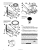
32
34
36
33
38
39
37
35
40
41
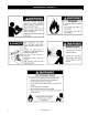
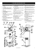
Natural gas and Propane main
burner with igniter assembly for
40k to 50k Btu/hr models
Figure 3
32 34
36
33
38
39
37
35
40
41
Natural gas and Propane
main burner with igniter
assembly for 60k to 75k
Btu/hr models
Figure 4
17
Figure 5
25
23
24
22
5
26
27
21
Figure 6
Vacuum relief valve
install per local
codes (not supplied
with heater).
Figure 7
Notes:
* Items not supplied with the water heater.
** The side recirculation loop connections may not be
used as the primary water inlet and outlet connections.
See “Combo Heating Inlet And Outlet Side Taps”
below.
*** Caution harness has 120 VAC In operation.
**** See “Planning The Vent System”, “Condensate” and
“Blower Assembly Installation” for more information.
REPLACEMENT PARTS AND DELIMING PRODUCTS
Replacement parts and recommended delimer may be
ordered through authorized servicers or distributors. When
ordering parts, provide complete model and serial numbers
(see rating plate), quantity and name of part desired.
Standard hardware items may be purchased locally.
COMBO HEATING INLET AND OUTLET SIDE TAPS
Models equipped with Combo Heating capabilities are
shipped with the two side plumbing taps OPEN (items
18 and 20 in Figure 1 and see also Figures 8 & 26). If
the heater is to be operated without using the side taps,
these openings must be closed with the two pipe plugs
supplied with the heaters.