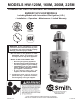
MODELS HW-120M, 160M, 200M, 225M COMMERCIAL GAS COPPER HEAT EXCHANGER WATER HEATER BURKAY UP-FLOW MODELS Including Models with Intermittent Pilot Ignition (I.I.D.) • Installation • Operation • Maintenance • Limited Warranty LOW LEAD CONTENT WARNING: If the information in these instructions are not followed exactly, a fire or explosion may result causing property damage, personal injury or death.
GENERAL SAFETY 2
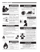
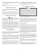
SAFE INSTALLATION, USE AND SERVICE Your safety and the safety of others is extremely important in the installation, use, and servicing of this water heater. Many safety-related messages and instructions have been provided in this manual and on the water heater to warn you and others of a potential injury hazard. Read and obey all safety messages and instructions throughout this manual.
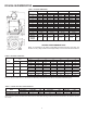
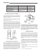
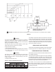
ROUGH-IN-DIMENSIONS TABLE 1 - ROUGH-IN DIMENSIONS Models HW-120M Dimensions Inches mm A 49 3/8 1254 B 30 3/8 772 C 23 5/8 600 D 20 3/4 527 E 5 1/2 140 F 10 254 G 11 13/16 300 H 6 152 J 26 11/16 678 K 20 3/4 527 L 1 1/4 NPT M 1 NPT N 1/2 NPT W 1 3/4 44 Approx. Shipping 120 lbs. 54 Kg.
FOREWORD This design complies with the current edition of the ANSI Standard Z21.10.3 for gas water heaters Vol. III Storage Water Heaters with input ratings above 75,000 BTU per hour Circulating and Instantaneous. The factory warranty will be void if the unit(s) have been improperly installed or operated. In addition to these instructions, the water heater(s) shall be installed in accordance with those installation regulations in force in the local area where the installation is to be made.
IF YOU EXPERIENCE AN OUT-OF-GAS SITUATION, DO NOT TRY TO RELIGHT APPLIANCES YOURSELF. Only trained LP professionals should conduct the required safety checks in accordance with industry standards. SHOULD OVERHEATING OCCUR OR THE GAS SUPPLY FAIL TO SHUT OFF, TURN OFF THE MANUAL GAS CONTROL VALVE TO THE WATER HEATER. Heater must be protected from freezing downdrafts during shutdown periods.
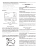
FEATURES TABLE 4. Control Device Factory Setting Field Adjustment 1950F (90.5°C) cut out temp. Heater Automatic Gas Shutoff Control Fixed 1900F (87.7°C) cut in temp. Non-adjustable 250 F (121°C) cut out temp. Heater Protector Switch Fixed 2000F (93.3°C) cut in temp. Non-adjustable 0 Tank Temperature Control Safety Flow Switch Field Supplied and Installed See Table 1 Adjust to Requirements Field Adjustable AUTOMATIC GAS SHUTOFF CONTROL The automatic gas shutoff control, fig.
4. Discontinues ignition spark when pilot flame is established. The S8600 / S8610 control used on propane gas models provides safety lockout if pilot fails to ignite within the pilot flame establishing period. The S-8600 / S-8610 control used on natural gas models continues trial for ignition until pilot flame is established. Follow the same oiling procedure if a replacement circulating pump is installed into the system. 5. After proof-of-pilot flame, opens the main valve.
CAUTION: The paddle must be trimmed at the dotted arc. It must not touch the pipe or any restrictions when installed. FIGURE 5 The installer is cautioned to follow the manufacturer’s instructions exactly when inserting this switch into a pipe tee. This is necessary in order to assure positive action of the switch with water flow. Once the minimum flow rate (Table 5) through the heater is reached, the safety flow switch contacts close and consequently, main burner operation is achieved.
INSTALLATION INSTRUCTIONS IMPORTANT For water heater installation in locations with elevations above 2,000 feet (610M), refer to HIGH ALTITUDE INSTALLATIONS section of this manual for input reduction procedure. Strict adherence to installation wiring diagrams shown in this manual is required to prevent constant pump operation when the system temperature control is satisfied, otherwise the warranty is void as stipulated under item 2a (6) of the LIMITED WARRANTY.
CONFINED SPACE When drawing combustion and dilution air from inside a conventionally constructed building to a confined space, such a space shall be provided with two permanent openings, ONE IN OR WITHIN 12 INCHES (30.5cm) OF THE ENCLOSURE TOP AND ONE IN OR WITHIN 12 INCHES (30.5cm) OF THE ENCLOSURE BOTTOM. Each opening shall have a free area of at least one square inch per 1000 Btuh (2,225mm2/Kw) of the total input of all appliances in the enclosure, but not less than 100 square inches (645 square cm).
Temperature-Pressure Relief Valve is not intended for the constant relief of thermal expansion. A properly sized thermal expansion tank must be installed on all closed systems to control the harmful effects of thermal expansion. Contact a local plumbing service agency to have a thermal expansion tank installed. Your local code authority may have other specific relief valve requirements not covered in this section.
PIPING DIAGRAMS DANGER TEMPERATURE SETTING SHOULD NOT EXCEED SAFE USE TEMPERATURE AT FIXTURES. SEE WATER TEMPERATURE CONTROL WARNING ON PAGE 20. IF HIGHER PREHEAT TEMPERATURES ARE NECESSARY TO OBTAIN ADEQUATE BOOSTER OUTPUT, ADD AN ANTI-SCALD VALVE FOR HOT WATER SUPPLIED TO FIXTURES.
DANGER TEMPERATURE SETTING SHOULD NOT EXCEED SAFE USE TEMPERATURE AT FIXTURES. SEE WATER TEMPERATURE CONTROL WARNING ON PAGE 20. IF HIGHER PREHEAT TEMPERATURES ARE NECESSARY TO OBTAIN ADEQUATE BOOSTER OUTPUT, ADD AN ANTI-SCALD VALVE FOR HOT WATER SUPPLIED TO FIXTURES.
DANGER TEMPERATURE SETTING SHOULD NOT EXCEED SAFE USE TEMPERATURE AT FIXTURES. SEE WATER TEMPERATURE CONTROL WARNING ON PAGE 21. IF HIGHER PREHEAT TEMPERATURES ARE NECESSARY TO OBTAIN ADEQUATE BOOSTER OUTPUT, ADD AN ANTI-SCALD VALVE FOR HOT WATER SUPPLIED TO FIXTURES.
GAS CONNECTIONS DO NOT USE MATCHES, CANDLES, FLAME OR OTHER SOURCES OF IGNITION FOR THIS PURPOSE. WARNING THE INLET GAS PRESSURE MUST NOT EXCEED THE VALUE SPECIFIED BY THE MANUFACTURER ON THE RATING PLATE (10.5” W.C. - NATURAL GAS, 13.0” W.C. - PROPANE GAS). EXPOSURE TO HIGHER GAS SUPPLY PRESSURE MAY CAUSE DAMAGE TO THE GAS VALVE WHICH COULD RESULT IN FIRE OR EXPLOSION.
A minimum gas supply pressure of 4.5” W.C. (1.12kPa) for natural gas and 11” W.C. (2.74kPa) for propane gas is required for purposes of input adjustment. when the heater leaves the factory. Using the individual wiring diagrams on the installation diagrams, the installer connects his wiring to terminals in the heater(s) mounted junction box as shown.
OPERATION Any time work is done on the gas supply system perform a leak test to avoid the possibility of fire or explosion. IMPORTANT 1. For test pressures exceeding 1/2 psi (3.45 kPa) disconnect the water heater and its Main Gas Shutoff Valve from the gas supply piping system during testing, see Figure 21. The gas supply line must be capped when disconnected from the water heater. Only qualified personnel shall perform the initial firing of the heater.
OPERATING INSTRUCTIONS FOR I.I.D. MODELS The I.I.D. models have an automatic intermittent spark ignition system, figure 3, mounted on the jacket at the front of the heater which ignites the pilot gas whenever system controls call for heat. Start the unit in accordance with the instructions on the operating label attached to the heater. These instructions are repeated in the following.
1. Turn the gas valve control knob to “OFF”, (See page 19). 2. Attach a pressure gauge or a manometer to the outlet pressure tap, figure 13 and refer to table 3 for correct manifold pressure. 3. Fire the heater by turning the gas valve control knob to “ON”. 4. Use this formula to “clock” the meter. Be sure that other gas consuming appliances are not operating during this interval.
SERVICE INFORMATION The installer may be able to observe and correct certain problems 5. Restore electrical power and gas supply to heater. which may arise when the unit is put into operation. HOWEVER, • Check for gas leaks and proper heater and vent operation. it is recommended that only qualified service personnel, using appropriate test equipment, be allowed to service the heater. I.I.D.
The control settings are fixed at 1950F (90.5°C) cut-out and 1900F (87.7°C) cut-in. Reduced water flow due to lime scale accumulation is one cause of frequent automatic gas shutoff control operations. Refer to “PREVENTIVE MAINTENANCE” section for deliming instructions. If this non-adjustable control is out of calibration, replace control. THERMAL BALANCER Figure 15 shows the internal wiring of the thermal balancer.
RELIEF VALVE CAUTION DO NOT USE A NYLON BRUSH OR OTHER STATIC CREATING MATERIAL TO CLEAN DUST AND CARBON DEPOSITS FROM HEATING SURFACES AND VENT. At least twice a year the system relief valves should be checked to ensure that they are in operating condition. To check a relief valve, lift the lever at the end of the valve several times. The valve should seat properly and operate freely. SUCH DEPOSITS ARE FLAMMABLE AND MAY BE IGNITED BY STATIC ELECTRICITY.
The usage of water softening equipment greatly reduces the hardness of the water. However, this equipment does not always remove all of the hardness (lime). For this reason it is recommended that a regular schedule for deliming be maintained. The time between cleaning will vary from weeks to months depending upon water conditions and usage. A change of approximately 50F in the normal temperature rise through the heater is usually an indication that scale should be removed.
CHECKOUT The checkout sequence should be used as an on-the-job troubleshooting guide to identify the cause of incorrect system operation and suggest a remedy for its correction. examined before using the checkout procedure. Be sure to refer to the correct piping - wiring diagram and checkout for the type of system that is installed.
CHART 2 S8600/S8610 (NATURAL GAS AND LP GAS) INTERMITTENT PILOT SYSTEM TROUBLESHOOTING NO SPARK AT PILOT BURNER Turn gas supply off. Replace ignition module. NO Is voltage (24 Vac) across the 24 V terminals on “Call for heat”? YES Is voltage (24 Vac) across the PV & MV/PV terminals on “call for heat”? NO NOTE: (FOR LP MODELS ONLY) Pilot valve will be de-energized if module goes into lockout condition.
CHART 2 S8600/S8610 (NATURAL GAS AND LP GAS) INTERMITTENT PILOT SYSTEM TROUBLESHOOTING SPARK AT PILOT BURNER BUT PILOT WILL NOT LIGHT Ensure all manual shutoff valves are fully open; All filters are clean; All gas connections are gas tight; Pilot tubing is not damaged, obstructed or kinked; and pilot orifice is unclogged. Check for air in gas line, purge (bleed) line if necessary. NO Attach wires firmly.
CHART 2 S8600/S8610 (NATURAL GAS AND LP GAS) INTERMITTENT PILOT SYSTEM TROUBLESHOOTING PILOT BURNER LIGHTS BUT MAIN BURNER DOES NOT LIGHT Correct the situation by consulting the installation or user’s manual on how to adjust pilot flame. Replace ignition module. NO Attach wires firmly.
CHART 3 LED STATUS AND TROUBLE SHOOTING The following procedures are provided as a general guide. Any module should be replaced if it does not perform properly or checkout on troubleshooting. In addition, replace any module if it is wet or looks like it has ever been wet.
CHART 4 CONTINUOUS RETRY MODEL M - GREEN LED STATUS CODES Green LED Flash Code (X + Y) a Indicates Next System Action Recommended Service Action not applicable none OFF No “Call for Heat” Flash Fast Startup - Flame sense calibration not applicable none Heartbeat Normal Operation not applicable none 2 5 minute Retry Delay -Pilot flame not detected during trial for ignition. Initiate new trial for ignition after retry delay completed.
CHART 5 LOCKOUT MODEL H - GREEN LED STATUS CODES Green LED Flash Code (X + Y) a Indicates Next System Action Recommended Service Action OFF No “Call for Heat” not applicable none Flash Fast Startup - Flame sense calibration not applicable none Heartbeat Normal Operation not applicable none 3 Recycle - Flame failed during run. Initiate new trial for ignition. Flash code will remain through the ignition trial until flame is proved.
NOTES 32
NOTES 33
NOTES 34
COMMERCIAL CIRCULATING WATER HEATER LIMITED WARRANTY EFFECTIVE WHAT'S NOT COVERED If within FIVE years after initial installation of the water heater, a heat exchanger or gas burner shall prove upon examination by the warrantor to be defective in material or workmanship, the warrantor, at his option will exchange or repair such part or portion.
500 Tennessee Waltz Parkway, Ashland City, TN 37015 Technical Support: 800-527-1953 • Parts: 800-433-2545 www.hotwater.com Copyright © 2015 A. O. Smith Corporation, All rights reserved.