
Install Instructions

Residen al Standard Gas Water Heater Use and Care Guide • 19
INSTALLATION
Residen al Standard Gas Water Heater Use and Care Guide • 19
INSTALLATION
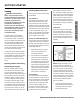
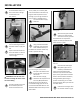
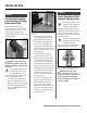
Step 6:
Connect the Tempera-
ture and Pressure (T&P)
Relief Valve/Pipe
Most T&P Relief Valves are pre-
installed at the factory. In some cases,
they are shipped in the carton and
must be installed in the opening
marked “T&P Relief Valve” and accord-
ing to local codes.
Figure 25 - Temperature and Pressure Relief Valve
WARNING! To avoid serious injury
or death from explosion, install a T&P
Relief Valve according to the following
instruc ons:
1
If the T&P Relief Valve was not
factory installed, install the
new T&P Relief Valve that
came with your water heater. Do not
reuse an old T&P Relief Valve.
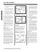
• The discharge pipe should be at
least 3/4” inside diameter and
sloped for proper drainage. Install
it to allow complete drainage of
both the T&P Relief Valve and the
discharge pipe.
Figure 26 - Temperature and Pressure Relief
Valve Pipe
• The discharge pipe must not be
smaller than the pipe size of the
T&P Relief Valve. The pipe must
also be able to withstand 250°F
(121°C) without distor on. Use
only copper or CPVC pipe. Do not
use any other type of pipe, such as
PVC, iron, fl exible plas c pipe, or
any type of hose.
• Terminate the discharge pipe a
maximum of six inches above a
fl oor drain or outside the building.
Do not drain the discharge pipe
into the drain pan; instead pipe it
separately to an adequate drain.
In cold climates, terminate the dis-
charge pipe inside the building to
an adequate drain. Outside drains
could freeze and obstruct the
drain line—protect the discharge
pipe from freezing.
• Do not place any valve or other
restric on between the tank and
T&P Relief Valve. Do not cap,
block, plug, or insert any valve
between the T&P Relief Valve and
the end of the discharge pipe. Do
not insert or install any reducer in
the discharge pipe.
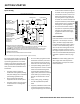
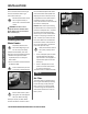
Step 7:
Install Shutoff and Ther-
mosta c Mixing Valves
1
If one is not already installed,
install a manual shutoff valve
in the cold water line that
supplies the water heater. Install the
shutoff valve near the water heater so
that it is readily accessible. Only use a
full-fl ow ball or gate valve compa ble
with potable water.
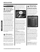
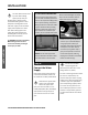
2
Install a Thermosta c Mixing
Valve at each point-of-use (for
example, kitchen sink,
bathroom sink, bath, shower) per the
valve manufacturer’s instruc ons.
Figure 27 - Install Thermostatic Mixing Valves at
each point where hot water will be used.
WARNING! Even if the water
heater’s thermostat is set to a rela-
vely low temperature, hot water can
scald. Install Thermosta c Mixing
Valves at each point-of-use to reduce
the risk of scalding.