AOC 15/50 Wind Turbine Generator User Manual DOC012R02 Nov 2001 U.S. $55.00 Atlantic Orient Corporation Farrell Farm Road, Rt 5 North P.O. Box 1097 Norwich, VT 05055 Tel: 802-649-5446 Fax: 802-649-5404 AOC@Vermontel.net www.aocwind.
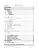
i Table of Contents WARNING........................................................................................... iv DISCLAIMER ...................................................................................... v Part I ....................................................................................................... 1 1.0 Introduction........................................................................................ 3 1.1 Manual Use ......................................................
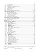
ii 6.1 6.2 6.3 6.3.1 6.4 6.5 6.6 Tower Assembly ....................................................................................................... 36 Tower Erection.......................................................................................................... 37 Wind Turbine Component Preparation ...................................................................... 38 Tip Brake Installation ............................................................................................
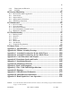
iii 9.4.4 9.4.5 Temperature and Elevation .................................................................................... 82 Acoustics............................................................................................................... 83 10.0 System Monitoring .......................................................................... 85 10.1 10.2 10.3 10.4 10.5 Kilowatt-Hour Meter Applications ............................................................................ 86 Anemometers ....
iv WARNING THE INSTALLATION OF A WIND TURBINE GENERATOR REQUIRES SPECIALIZED SKILLS, EQUIPMENT AND EXPERIENCE. INFORMATION SUPPLIED BY ATLANTIC ORIENT CORPORATION AND ITS SUPPLIERS, FOR THE PURPOSES OF INSTALLING, OPERATING AND MAINTAINING ALL EQUIPMENT, ASSUMES THAT PERSONNEL HAVE THE SKILLS, EXPERIENCE AND EQUIPMENT NEEDED. NO ONE SHOULD ATTEMPT TO CLIMB TOWERS AND OPERATE OR MAINTAIN WIND TURBINES WITHOUT THE NECESSARY SKILLS, EXPERIENCE, TOOLS AND SAFETY EQUIPMENT.
v DISCLAIMER This manual is intended as a guide only. It should not be considered as a replacement for professional services or as a definitive text for assembling and installing wind turbine generating systems. Atlantic Orient Corporation, its affiliates and representatives make no warranties either expressed or implied that the information contained herein is accurate or complete. Atlantic Orient Corporation makes no warranties of merchantability or fitness for a particular purpose and/or site.
vi NOTICE: Use of the material contained in this document is subject to the warning on page Iv and the disclaimer on page v of this document.
Part I 1 Part I NOTICE: Use of the material contained in this document is subject to the warning on page Iv and the disclaimer on page v of this document.
Part I NOTICE: 2 Use of the material contained in this document is subject to the warning on page Iv and the disclaimer on page v of this document.
3 1.0 Introduction Photo Courtesy of KEA KOTZEBUE ELECTRIC ASSOCIATION WIND FARM NOTICE: Use of the material contained in this document is subject to the warning on page Iv and the disclaimer on page v of this document.
1.0 Introduction 1.1 4 Manual Use This manual has been developed for use by qualified technicians for the operation and maintenance of the wind turbines manufactured by Atlantic Orient Corporation (AOC). The information provided specifically applies to the AOC 15/50 wind turbine and is valid for both the 50 Hz and the 60 Hz versions, unless otherwise stated.
1.0 Introduction 1.2 5 Cautionary Icons 1.2.1 Warning Icon The warning icon denotes actions or procedures that may lead to equipment failure or death to personnel, if not carried out correctly. 1.2.2 Caution Icon The caution icon denotes actions or procedures that may lead to severe equipment damage or injury to personnel, if not carried out correctly. 1.3 Personnel Definitions 1.3.
1.0 Introduction 6 1.3.3 Maintenance Personnel Maintenance personnel are defined as technical staff with training and/or experience in climbing towers and the use of safety equipment, as well as a firm understanding of the wind turbine’s mechanical and control system. Knowledge of rigging and lifting heavy industrial machinery may also be necessary. ONLY TRAINED AND QUALIFIED TECHNICIANS SHOULD ATTEMPT TO CLIMB A WIND TURBINE TOWER AND SHOULD USE OSHA/ANSI APPROVED PRACTICE AND EQUIPMENT.
7 2.0 System Description Photo Courtesy of KEA ALASKA FIELD SERVICE NOTICE: Use of the material contained in this document is subject to the warning on page Iv and the disclaimer on page v of this document.
2.0 System Description 8 The following sections provide a general description of the AOC 15/50 and its control system. 2.1 General Description and Features of the Turbine The designation 15/50 refers to the 15 m diameter wood/epoxy or fibreglass rotor and its projected rated output of 50 kW. This rated output is achieved at 12 m/s (26.8 mph) by the 50 Hz version and at 11.3 m/s (25.3 mph) by the 60 Hz one.
2.0 System Description 9 Figure 2-1 AOC 15/50 Wind turbine NOTICE: Use of the material contained in this document is subject to the warning on page Iv and the disclaimer on page v of this document.
2.0 System Description 10 Figure 2-2 AOC 15/50 Wind turbine assembly, drive train detail Figure 2-3 AOC 15/50 Drive train assembly NOTICE: Use of the material contained in this document is subject to the warning on page Iv and the disclaimer on page v of this document.
2.0 System Description 2.2 11 Control System Description The following parameters are monitored by the wind turbine’s control system. It initiates shutdowns when faults have been detected to protect the wind turbine from mechanical and electrical damage.
2.0 System Description 12 inertia of the rotor and drive train that must be overcome initially. Once the wind speed conditions are met, the parking brake is released and the generator starts rotating, at which point PLC starts monitoring the generator rotor speed. Once the parking brake has released and the rotor speed is in band,the wind turbine is connected to the grid automatically.
13 3.0 Safety Guidelines Photo Courtesy of BED TOWER ERECTION AT BURLINGTON ELECTRIC DEPARTMENT NOTICE: Use of the material contained in this document is subject to the warning on page Iv and the disclaimer on page v of this document.
3.0 Safety Guidelines 14 This section covers the safety information needed by a technician to install, operate and maintain the AOC 15/50 safely. Special safety considerations for specific circumstances are highlighted throughout this manual. CAUTION THE RESPONSIBILITY FOR SAFE CONDUCT AND OPERATION ULTIMATELY RESTS WITH THE OPERATOR/ TECHNICIAN. 3.
3.0 Safety Guidelines 3.3 15 Start-up and Shut-down Safety Procedures Prior to starting up a wind turbine, the operator should warn any personnel in the area that it will be started and to visually inspect the area to ensure that they are clear of it. In addition, the operator should ensure that there are no visual signs indicating problems with the wind turbine. During a shutdown sequence, no personnel should approach the wind turbine, until it has come to a complete stop. 3.
3.0 Safety Guidelines 16 Ropes may replace straps provided care is taken not to damage the blade surface; cables or chains should not be used. CAUTION NEVER USE METAL CHAINS OR CABLES TO SECURE THE BLADE, SINCE DAMAGE TO THE BLADE IS LIKELY. 3.5 Climbing Safety For all activities where persons could be subject to a fall of 1.8 m (6 ft) or more, appropriate fall protection equipment should be used, which should be fastened to a secure anchor point, preferably above the climber.
3.0 Safety Guidelines 17 ground personnel. The area around the tower should also be roped off with appropriate warning signs indicating falling objects. Finger rings should not be worn while climbing structures or vehicles, or while performing any task where the ring might be caught under or snagged by a projecting or moving item. 3.6 Electrical Safety WARNING WHENEVER POSSIBLE, ELECTRICAL EQUIPMENT SHOULD BE DE-ENERGIZED AND GROUNDED PRIOR TO SERVICING.
3.0 Safety Guidelines 18 WARNING NO SERVICE WORK SHOULD BE PERFORMED ON A WIND TURBINE IN THE PRESENCE OR THREAT OF LIGHTING. WET AND/OR ICE LADEN TOWERS SHOULD NOT BE CLIMBED. EXTERIOR ELECTRICAL EQUIPMENT SHOULD NOT BE WORKED ON DURING SIGNIFICANT PRECIPITATION. 3.8 Emergency Procedure CAUTION WHEN A HAZARD EXISTS, PERSONNEL SAFETY MUST BE ENSURED BEFORE ADDRESSING THE SAFETY OF THE WIND TURBINE EQUIPMENT.
3.0 Safety Guidelines 19 WARNING DO NOT ATTEMPT TO OPERATE THE AOC 15/50 WITHOUT AOC CONSULTATION AFTER A SERIOUS EVENT HAS OCCURRED. AOC RECOMMENDS A COMPLETE INSPECTION OF THE TURBINE AND ITS COMPONENTS BY TRAINED PERSONNEL AFTER ANY SUCH EVENT. FAILURE TO DO SO MAY RESULT IN POOR PERFORMANCE, INJURY OR DEATH. NOTICE: Use of the material contained in this document is subject to the warning on page Iv and the disclaimer on page v of this document.
3.0 Safety Guidelines NOTICE: 20 Use of the material contained in this document is subject to the warning on page Iv and the disclaimer on page v of this document.
Part II 21 Part II NOTICE: Use of the material contained in this document is subject to the warning on page Iv and the disclaimer on page v of this document.
Part II NOTICE: 22 Use of the material contained in this document is subject to the warning on page Iv and the disclaimer on page v of this document.
23 4.0 Planning and Installation Checklist Photo Courtesy of KEA SITE CONSTRUCTION AT KOTZEBUE ELECTRIC ASSOCIATION NOTICE: Use of the material contained in this document is subject to the warning on page Iv and the disclaimer on page v of this document.
4.0 Planning and Installation Checklist 24 The following sections are intended to assist customers in addressing the relevant installation details in a logical sequence. Although most points apply to both large and small projects, not all will apply to every project. To ensure thorough planning, it is strongly recommended that customers understand why a particular detail is or is not appropriate to their installation.
4.0 Planning and Installation Checklist • • • • 25 Line protection required Cogeneration standards for small power producers Interconnection hardware and wiring standards System operation requirements: § Voltage regulation § Power factor § Protective devices § Utility/wind turbine interface responsibilities To interface with the utility network correctly all power factor correction capacitors or unique loads connected to the utility system need to be identified by the customer.
4.0 Planning and Installation Checklist 26 The following list contains suggested documentation to prepare in advance and have on hand to ensure efficient and proper site development, as well as for submittal for the necessary approvals: • • • • • • • • • • • 4.
4.0 Planning and Installation Checklist 4.6 27 Electrical Planning Considerations The local wiring inspector should review the design of the electrical installation before work starts at the site. The following items should be considered in the design/installation of the electrical system: • • • • • • • • • • • • • 4.
4.0 Planning and Installation Checklist • • • • 4.8 28 Platform or bucket for blade installation Appropriate safety equipment Crane Forklift or boom truck Installation Personnel Considerations The installation and maintenance of a wind turbine requires specialized skills, equipment and experience. AOC assumes that all installation and operation personnel will have these skills, experience and equipment.
4.0 Planning and Installation Checklist Day 1: • • • • • • • • Plan and prepare erection Assemble tower Test generator and use it as a motor to test drive train Clean blades and install tip brake cable Prepare tip brake studs and cavity Prepare blade bolt inserts Attach twist cable Install two of three blades if time permits (fork lift, boom truck, etc.
4.0 Planning and Installation Checklist NOTICE: 30 Use of the material contained in this document is subject to the warning on page Iv and the disclaimer on page v of this document.
31 5.0 Site Preparation Photo Courtesy of BED FOUNDATION CONSTRUCTION AT THE BURLINGTON ELECTRIC DEPARTMENT PROJECT NOTICE: Use of the material contained in this document is subject to the warning on page Iv and the disclaimer on page v of this document.
5.0 Site Preparation 32 WARNING DURING THE INSTALLATION OF A WIND TURBINE, THE SITE SHOULD BE MAINTAINED SO THAT IT DOES NOT PRESENT A SAFETY RISK/HAZARD TO PERSONNEL. The following sections discuss some of the siting factors, which must be considered before the wind turbine arrives. 5.1 Site Access Access to the site is a prime consideration when installing a wind turbine. Limitations in site access will determine the type of installation and equipment that can be used.
5.0 Site Preparation 33 It may be advisable to excavate trenches for power and control cables at the time of digging the foundations. For wire and cable information, refer to Appendix M. CAUTION CAREFUL MEASUREMENT AND USE OF AN ACCURATE ANCHOR BOLT TEMPLATE BEFORE, DURING AND AFTER CONCRETE POURING CAN MINIMIZE ALIGNMENT PROBLEMS OR FOUNDATION REPAIRS. 5.3 Receiving the Wind Turbine at the Site Wind turbines are often installed on uneven terrain.
5.0 Site Preparation NOTICE: 34 Use of the material contained in this document is subject to the warning on page Iv and the disclaimer on page v of this document.
35 6.0 Tower and Wind Turbine Generator Installation Photo Courtesy of BED TOWER ASSEMBLY AT THE BURLINGTON ELECTRIC DEPARTMENT PROJECT NOTICE: Use of the material contained in this document is subject to the warning on page Iv and the disclaimer on page v of this document.
6.0 Tower and Wind Turbine Generator Installation 36 The following sections describe the assembly of the tower, as well as its erection and the installation of the wind turbine generator. 6.1 Tower Assembly For the assembly details refer to the manufacturer’s instruction packet shipped with the tower. The tower assembly drawings for the standard 24.4 m (80 ft) tower are supplied in Appendix C; for those of the 30.5 m (100 ft) tower see Appendix D.
6.0 Tower and Wind Turbine Generator Installation 37 NOTE: A template identical to the anchor bolt template can be bolted to the bottom leg flanges during tower assembly to insure a proper fit during the tower erection. Using both templates should theoretically allow all bolts to be torqued before erection. 6.2 Tower Erection Appendix G contains the Installation QA checklist that should be used during the installation process.
6.0 Tower and Wind Turbine Generator Installation 38 after which the tension on the crane cable can be relaxed. A technician should verify that the tower top is level by climbing the tower. Any adjustments required to level the tower top should be made by adjusting the anchor nuts. The 1½ “ anchor bolt nuts should be torqued to AISC snug tight standards after the tower has been erected; snug tight being defined as the tightness needed to bring all plies in a joint into firm contact.
6.0 Tower and Wind Turbine Generator Installation 39 CAUTION THE BLADES SHOULD NOT BE SCRATCHED OR GOUGED DURING SITE HANDLING AS THIS CAN CAUSE A LOSS OF ROTOR PERFORMANCE AND/OR BLADE DEGRADATION FROM ENVIRONMENTAL EFFECTS. The string in the conduit should be used to pull a #10 gage wire through the conduit. The blade cable should then be attached to the wire (with tape, for example) and pulled through the blade conduit, with the molded 3-pin connector at the root end of the blade.
6.0 Tower and Wind Turbine Generator Installation 40 Figure 6-1 Parking brake manual release Figure 6-2 Tip brake installation NOTICE: Use of the material contained in this document is subject to the warning on page Iv and the disclaimer on page v of this document.
6.0 Tower and Wind Turbine Generator Installation 6.4 41 Blade Installation This procedure should be carried out by a minimum of three technicians. Each blade weighs 135 kg (300 lbs) and can be lifted by a crew of three or four or using equipment such as a back hoe or a boom truck fitted with nylon slings or ropes. Metal slings or chains should never be used to move a blade. CAUTION NICKS OR GOUGES IN THE BLADE SURFACE CAN AFFECT THE PERFORMANCE AND THE EXPECTED LIFE OF THE BLADE SIGNIFICANTLY.
6.0 Tower and Wind Turbine Generator Installation 42 DO NOT SUBSTITUTE BOLTS. Only the AOC supplied Grade 8, fine thread bolts, 5/8" x 3", should be used to secure the blades to the hub. The tip brakes can be unlatched or removed (if necessary) to prevent damage during the mounting process. The four corner bolts on the blade should be installed, initially without the washers, to hold the blade in place. The pitch tool should be inserted first, in slot #1 (see Figure 6.
6.0 Tower and Wind Turbine Generator Installation 43 Figure 6-5 Yaw lock Figure 6-6 Tower top casting NOTICE: Use of the material contained in this document is subject to the warning on page Iv and the disclaimer on page v of this document.
6.0 Tower and Wind Turbine Generator Installation 44 Blade #1 Turbine on pallet Ground level Figure 6-7 Positioning the blade for attachment 4 Corner Bolts Figure 6-8 Bolting blade to a hub The blade pitch can be adjusted to set the peak power production and to accommodate various wind resources. For pitch setting, consistency between blades and optimum power capture, AOC recommends that a pitch tool be used which may be purchased from AOC.
6.0 Tower and Wind Turbine Generator Installation 45 aligned properly and be seated completely in the slot counter bore of the hub. If a washer becomes misaligned while torque is applied, the bolt must be loosened and the washer realigned. For the attachment of the second blade, the hub is rotated so that the blade can be mounted with its tip supported, as was done for the first blade. The first blade will need to be supported initially by slings attached to a boom truck or crane.
6.0 Tower and Wind Turbine Generator Installation 46 Blade #1 Blade #2 Ground Figure 6-11 Attachment of the second blade 6.5 Lift Preparation CAUTION TOWERS AND DRIVE TRAIN ASSEMBLIES SHOULD NOT BE LIFTED INTO POSITION IN WINDS ABOVE 9 M/S (20 MPH), DURING LOW VISIBILITY OR WHEN LIGHTNING COULD POSSIBLY OCCUR. ALL TOWER AND GROUND PERSONNEL MUST BE PROPERLY TRAINED, BRIEFED AND FITTED OUT WITH SAFETY EQUIPMENT.
6.0 Tower and Wind Turbine Generator Installation 47 before hoisting the wind turbine generator will make alignment with the tower easier. The timing of yaw lock release should be determined by trained personnel. Photo Courtesy of KEA Figure 6-12 Lifting of tilt down tower at Kotzebue Electric Association The large crane should lift the wind turbine generator using two slings as shown in Figure 6-13. The weight of the wind turbine is approximately 2,480 kg (5,450 lbs.).
6.0 Tower and Wind Turbine Generator Installation 48 technician standing on a platform (see Figure 6-14). The same procedures for attaching and aligning the third blade should be used as were described in Section 6.4. APPROXIMATE C. G. LINE Figure 6-13 Wind turbine generator lift When all blades and tip brakes have been mounted correctly, the parking brake should be engaged and a tagline attached to the two downward pointing blades, around the tip brake hinge point.
6.0 Tower and Wind Turbine Generator Installation 49 Third Blade Attached APPROX. 13 Ft Figure 6-14 Third blade attachment CAUTION THE PARKING BRAKE MUST BE PROPERLY ENGAGED, TO LOCK ALL ROTATING PARTS INTO POSITION, PRIOR TO LIFTING THE WIND TURBINE GENERATOR. NOTICE: Use of the material contained in this document is subject to the warning on page Iv and the disclaimer on page v of this document.
6.0 Tower and Wind Turbine Generator Installation 6.6 50 Lifting and Securing the Wind Turbine ONLY TRAINED AND QUALIFIED TECHNICIANS SHOULD ATTEMPT TO CLIMB A WIND TURBINE TOWER AND SHOULD USE OSHA/ANSI APPROVED PRACTICE AND EQUIPMENT. ANY ACTIVITIES WHERE PERSONS COULD BE SUBJECT TO A FALL OF SIX FEET OR MORE SHOULD BE PERFORMED USING APPROPRIATE FALL PROTECTION EQUIPMENT FASTENED TO A SECURE ANCHOR POINT. SEE CHAPTER 3 FOR A DESCRIPTION OF SAFETY EQUIPMENT AND SECURE ANCHOR POINTS.
6.0 Tower and Wind Turbine Generator Installation 51 WARNING THE PARKING BRAKE OF THE WIND TURBINE SHOULD NEVER BE LEFT DISENGAGED, AS THIS MAY CAUSE SEVERE INJURY. WIND TURBINE COMPLETE INSTALLATION IN MOROCCO NOTICE: Use of the material contained in this document is subject to the warning on page Iv and the disclaimer on page v of this document.
52 NOTICE: Use of the material contained in this document is subject to the warning on page Iv and the disclaimer on page v of this document.
53 7.0 Electrical Installation Photo Courtesy of BED UTILITY INTERFACE NOTICE: Use of the material contained in this document is subject to the warning on page Iv and the disclaimer on page v of this document.
7.0 Electrical Installation 54 The following sections discuss the wind turbine wiring and utility connection requirements and procedures. Wire connections to the three-phase control box, dynamic brake boxes and twist cable junction box are site specific, but should follow the general guidelines and wiring drawings available from AOC. 7.1 Electrical Interface to Utility The utility interface is site specific and must be coordinated with the local utility or other responsible party.
7.0 Electrical Installation NOTICE: 55 Use of the material contained in this document is subject to the warning on page Iv and the disclaimer on page v of this document.
7.0 Electrical Installation 56 CAUTION AFTER THE POWER COLLECTION INTERFACE HAS BEEN INSTALLED, ALL POWER CABLES AND WIRES TO THE WIND TURBINE MUST BE DE-ENERGIZED. ALL ELECTRIC DISCONNECTS FEEDING INTO THE WIND TURBINE MUST BE LOCKED OUT AND TAGGED OUT. 7.2 Wiring and Cable Requirements The following sections discuss the power, control and anemometer cable requirements. 7.2.
7.0 Electrical Installation NOTICE: 57 Use of the material contained in this document is subject to the warning on page Iv and the disclaimer on page v of this document.
7.0 Electrical Installation 58 7.2.2 Anemometer Mast and Cable Wiring The AOC 15/50 uses a dual anemometer based control system for increased reliability. Figure 73 shows a typical anemometer.
7.0 Electrical Installation 7.3 59 Control Box Connections Wires should be run in a conduit to the control box based on convenience, safety and applicable standards. Non-NEMA 4 electronic enclosures must be housed in a weatherproof service structure. However, it is recommended that all enclosures be housed in a weatherproof structure to facilitate maintenance in all weather conditions. Wires from the control box to the tower base should run in a conduit.
7.0 Electrical Installation 7.4 60 Twist Cables and Junction Box The twist cable junction box should be mounted on the inside of a tower leg approximately 3.7 m (12 feet) above the tower base. This height may need to be adjusted, depending on twist cable length. The vertical cable droop must be approximately 1.8 m (6 ft) (see Appendix B). Two Unistrut, split pipe clamps are used to secure the box to the tower leg.
7.0 Electrical Installation 61 8.0 Function Tests and Commissioning NOTICE: Use of the material contained in this document is subject to the warning on page Iv and the disclaimer on page v of this document.
8.0 Function Tests and Commissioning 62 The following section describes the procedures for testing a wind turbine’s functions before it is officially commissioned. 8.1 Function Tests and Commissioning Prior to placing the wind turbine into initial service and after any maintenance and/or repair work, the following must be carried out and the commissioning/checkout test sheet must be completed (see Appendix H).
8.0 Function Tests and Commissioning • • 63 Test emergency shut down (See Section 9.3.8) Test low wind shut down (See Section 9.3.9) It is a good idea to observe the wind turbine running under normal conditions to verify its correct operation. After it has been observed in normal winds, it may be signed off and formally commissioned. 8.2 Generator Test Each generator should be run briefly to determine proper phase rotation.
8.0 Function Tests and Commissioning NOTICE: 64 Use of the material contained in this document is subject to the warning on page Iv and the disclaimer on page v of this document.
Part III 65 Part III NOTICE: Use of the material contained in this document is subject to the warning on page Iv and the disclaimer on page v of this document.
Part III NOTICE: 66 Use of the material contained in this document is subject to the warning on page Iv and the disclaimer on page v of this document.
67 9.0 Wind Turbine Operation AOC 15/50 Controller box NOTICE: Use of the material contained in this document is subject to the warning on page Iv and the disclaimer on page v of this document.
9.0 Wind Turbine Operation 68 WARNING BEFORE ENERGIZING THE SYSTEM, CAREFULLY REVIEW THIS CHAPTER AND ENSURE THAT ALL REQUIREMENTS ARE COMPLIED WITH. IMPROPER PROCEDURES IN ENERGIZING THE SYSTEM MAY CAUSE SEVERE INJURY OR DEATH FROM SHOCK. 9.1 Normal Operation This section contains a description of the operational functions of the wind turbine in normal conditions. Normal conditions are defined as those in which the wind turbine was designed to operate in (see Appendix A for the design specifications).
9.0 Wind Turbine Operation 69 9.1.1 Turbine TEST/OFF/ON Turbine OFF: This is the normal OFF mode. All brakes are deployed with the brake relays de-energized. The main contactor is de-energized, disconnecting the turbine from the grid. The PLC disregards all other sensors while the switch is set to OFF. The brake light should be ON. The high wind, brake cooling cycle or other fault lights may also be ON, subject to conditions. Turbine ON: This is the normal ON mode.
9.0 Wind Turbine Operation 70 The PLC monitors the system parameters continuously as shown in Table 9.1-2. When a system parameter is out of range or a fault has been registered, the PLC takes appropriate action by disconnecting and either parking or freewheeling the wind turbine. Following this, it will continue to monitor the parameters and faults, resetting the system once they have cleared. Rotor over-speed faults and parking brake undercurrent faults require to be reset manually.
9.
9.0 Wind Turbine Operation 72 9.1.4 Rotor Jog With the wind turbine in test mode the rotor jog switch will allow the operator to release the brakes and energize the main contactor, provided no high winds or fault conditions have been registered. It is not necessary to use the parking brake release switch with the rotor jog, as the rotor jog switch automatically releases all brakes before energizing the main contactor 9.1.
9.0 Wind Turbine Operation 73 Table 9.1-3 AOC 15/50 System indicating lights Function Color Description Turbine Ready Green ON: Turbine can be connected to the utility network. Turbine On Line Green ON: Turbine is connected to the utility network. Brakes Applied Red ON: Any of the brakes are deployed. OFF: When parking brake is released during parking brake release test. Brake Cooling Cycle Red ON: Turbine is waiting for brakes to cool (typically 15 minutes).
9.
9.0 Wind Turbine Operation 75 Figure 9-2 Inside of a typical turbine controller Figure 9-3 Capacitor box Figure 9-4 PLC THE SOFTWARE THAT OPERATES THE PLC IS DESIGNED BY AOC FOR EACH SPECIFIC APPLICATION, TO PROVIDE SAFE AND EFFICIENT WIND TURBINE CONTROL. MODIFICATIONS TO THE SOFTWARE, NOT AUTHORIZED BY AOC, COULD RESULT IN WIND TURBINE MALFUNCTION, DAMAGE TO IT AND/OR PERFORMANCE HAZARDS.
9.0 Wind Turbine Operation 76 9.1.7.1 PLC Inputs The following tables list and describe the input signals to the PLC controlling the AOC 15/50. Function Description Anemometer #1 0-5 VDC analog signal corresponds to 0-45 m/s (0-100 mph). Anemometer #2 0-5 VDC analog signal corresponds to 0-45 m/s (0-100 mph). Generator speed proximity switches #1 and #2 Pulse input to F/V converter. 1-5 VDC signal corresponds to 0 to 2,000 rpm. Watts Transducer Control 0-5 VDC analog signal corresponds to 0-8 kW.
9.0 Wind Turbine Operation 77 Table 9.1-6 PLC AC inputs 9.1.7.2 PLC Outputs The following tables describe the PLC outputs needed to control the AOC 15/50. AC outputs are used to control interposing relays and contactors for the various wind turbine functions. DC outputs are used for driving the LED indicators. Function Dynamic brake contactor Description Normally closed contacts are used to apply brake on loss of power. Parking brake relay Normally open contacts are used to apply brake on loss of power.
9.0 Wind Turbine Operation 78 Emergency Stop Pushed In: The emergency stop switch overrides all other switches. With the emergency stop pushed in, the wind turbine should come to a complete stop and de-energize immediately. All brakes deploy, the relays de-energize and the main contactor opens. In this mode, there is no power to the PLC output cards and the relays can not be energized. The wind turbine disconnects from the grid and remains so until the emergency stop is reset manually (pulled out).
9.0 Wind Turbine Operation 79 4. Reset the turbine test switch to OFF. 5. Observe the wind turbine; the parking brake should engage and the rotor should stop. WARNING THIS TEST SHOULD ONLY BE CARRIED OUT IN LOW WIND CONDITIONS. 9.3.3 Rotor Jog Test 1. 2. 3. 4. Set the turbine test switch to TEST. Turn the rotor jog switch to ON, connecting the wind turbine to the grid. The rotor should turn counterclockwise when viewed looking upwind.
9.0 Wind Turbine Operation 80 9.3.6 Speed Sensor Signal Test 1. Perform a rotor jog. 2. Measure the output voltage from the frequency to voltage converter. It should be approximately 3.75 VDC (50 Hz) or 4.5 VDC (60 Hz). 9.3.7 Normal Start-up/Shut-down Test 1. 2. 3. 4. In 5.4 - 9 m/s (12 - 20 mph) winds, turn the turbine switch to ON. The rotor should accelerate and the main contactor should close. Turn the turbine switch to OFF.
9.0 Wind Turbine Operation 81 During routine inspections in aggressive environments, particular attention should be directed at locating oxidation and blistered paint. If any such surface degradation is found, corrective action should be taken immediately; the corroded layer should be removed and either paint or a corrosion-inhibiting film, such as Soft Seal, should be applied.
9.0 Wind Turbine Operation 82 Wet snow may affect tip brake operation, possibly causing premature deployment or, in severe cases, damage due to the additional weight on the tip brake plate. Severe icing may also inhibit the tip brake from deploying correctly. Ice build-up on the anemometers can prevent a wind turbine from starting up. If it is already running, the anemometers may ice up before the blades, indicating conditions in which the wind turbine should be shut down.
9.0 Wind Turbine Operation 83 The example below illustrates the above formula: If a 50 kW wind turbine generates 50 kW at 13.4 m/s (30 mph) wind speed under standard conditions, what would the output be at an altitude of 1,980 m (6,500 feet) and 30°C (86°F)? Solution: Corrected Output = Standard Output *Ct *Ca Ps = 50 kW Ct = 519 = .951 86 + 460 C a = . 966 6500/1000 = .799 Corrected Output = (50kW) (.951) (.799) = 38.
9.0 Wind Turbine Operation NOTICE: 84 Use of the material contained in this document is subject to the warning on page Iv and the disclaimer on page v of this document.
85 10.0 System Monitoring Photo Courtesy of KEA KOTZEBUE ELECTRIC ASSOCIATION WIND FARM NOTICE: Use of the material contained in this document is subject to the warning on page Iv and the disclaimer on page v of this document.
10.0 System Monitoring 86 The following sections discuss the various monitoring systems of the AOC 15/50. 10.1 Kilowatt-Hour Meter Applications Some utilities may require the use of detented, unidirectional kilowatt-hour (kWh) meters: one to read the energy supplied by the utility and another to read the energy absorbed by it. This enables the utility to pay the avoided cost rate for the energy it buys and to charge the standard rate for the energy it consumes.
10.0 System Monitoring 87 production depends on a site's actual wind resources and conditions, and varies with wind turbine condition, altitude, temperature, topography and the proximity of other structures. It should be noted that most sites experience seasonal variations in wind resources and, therefore, in energy production. 10.5 Wind Energy Data Sheet The wind energy data sheet (see Appendix G) can assist evaluating AOC wind systems.
88 NOTICE: Use of the material contained in this document is subject to the warning on page Iv and the disclaimer on page v of this document.
89 11.0 Maintenance Photo Courtesy of KEA MAINTENANCE AT KOTZEBUE ELECTRIC ASSOCIATION NOTICE: Use of the material contained in this document is subject to the warning on page Iv and the disclaimer on page v of this document.
11.0 Maintenamce 90 The following sections contain the maintenance routines for the AOC 15/50. Note that not all of the maintenance listed has to be carried out at every scheduled check. See Appendix H for the maintenance schedule and record sheets. The maintenance record sheet should be copied and filled out for all maintenance and repairs carried out. See Appendix J for the fastener torque requirements.
11.0 Maintenamce 11.2 91 Tower Assembly Tower: The tower fasteners and members should be checked visually for damage. A random check of bolt torques should be carried out on flanges and braces (see Appendix J). All pal nuts should be in place and the anchor bolt nuts and hinge nuts should be seated snugly. Tower Top: All nuts and bolts on the tower top casting should be checked for proper torque (see Appendix M). The yaw lock should be checked for proper operation.
11.0 Maintenamce 92 The oil system should be checked for leaks and if it is equipped with a filter this should be replaced every year. 11.4 Power Distribution System/Controls Main Control Enclosure: • • • • • The panel should be inspected annually for burns, cracks and discoloration. The relays should be inspected annually for burned out coils and contacts.
11.0 Maintenamce 11.5 93 Maintenance Schedule The AOC 15/50 has been designed to reduce its maintenance requirements. However, to insure proper operation and peak performance, regular maintenance is recommended. Basic maintenance should be carried out once a year. Long-term maintenance requirements will vary from system to system. Certain items, such as the blade cleaning frequency, depend on the season and site conditions. Blades should be cleaned periodically to ensure peak energy capture.
94 NOTICE: Use of the material contained in this document is subject to the warning on page Iv and the disclaimer on page v of this document.
95 12.0 Troubleshooting Photo Courtesy of KEA TIP BRAKE TESTING AT KOTZEBUE ELECTRIC ASSOCIATION NOTICE: Use of the material contained in this document is subject to the warning on page Iv and the disclaimer on page v of this document.
12.0 Troubleshooting 96 This section contains a brief discussion of each major wind turbine component and the control system. See Section 12.7 for a summary of troubleshooting guidelines and recommendations. When troubleshooting it can generally be assumed that only one fault exists.
12.0 Troubleshooting 97 The rotor is brought to a complete stop by the parking brake, which is engaged after a delay of several seconds. Should the dynamic brake fail, the rotor can over-speed during the time delay period, in which case, the tip brakes may deploy centrifugally to prevent over-speed. Should any of the tip brakes deploy, other than for normal shutdowns and for reasons not related to a fault in their electrical circuits, the dynamic and parking brakes should be checked.
12.0 Troubleshooting 98 Figure 12.1-1 Dynamic brake schematic NOTICE: Use of the material contained in this document is subject to the warning on page Iv and the disclaimer on page v of this document.
12.0 Troubleshooting 99 Figure 12.1-2 Dynamic brake capacitor enclosure and power factor correction Figure 12.1-3 Dynamic brake resistors Figure 12.1-4 Stearns parking brake with speed pickup and temperature sensor NOTICE: Use of the material contained in this document is subject to the warning on page Iv and the disclaimer on page v of this document.
12.0 Troubleshooting 12.2 100 Generator The generator is a 66 kW, 3-phase induction type generator. It is connected to the grid as follows once the PLC controller signals that the relevant conditions have been met: the brakes are released, the rotor freewheels (coasts) up to synchronization speed and the main contactor closes. Various components can affect generator operation, which need to be checked if a generator problem is suspected.
12.0 Troubleshooting 101 The twist cable connects the wind turbine to its power and control cables, located at the base of the tower. It consists of a power cable and a control cable and eliminates any problems with the slip ring assembly as there are no moving parts. If the cable becomes physically twisted, i.e. more than ten complete turns, it must be disconnected, untwisted and re-connected. Depending on site conditions, this might have to be done every six months.
12.0 Troubleshooting 12.6 102 Yaw Bearing The yaw bearing allows the wind turbine to align itself with the wind. When the blades turn, the turbine should yaw into the proper position with the rotor facing downwind from the rest of the machine. If the wind turbine does not yaw correctly with respect to the wind, the yaw bearing should be greased and visually inspected. It should also be checked to see whether it is level; any necessary adjustments should be made via the anchor bolts at the tower base.
12.0 Troubleshooting 103 Parking brake does not release 1. Control fault 2. Loss of power 3. Wiring faulty 4. Solenoid faulty Dynamic brake does not engage 1. Electrical component failure Generator not turning 1. Transmission failure (with rotor rotating) necessary 1. Clear fault 2. Check grid connection 3. Check leads, connectors 4. Disassemble and check solenoid 1. Check dynamic brake panel, connections, capacitors and contractors and fuses 1. Disassemble and overhaul transmission 1.
12.0 Troubleshooting 104 Figure 12.7-1 Indicating Lights and Control Switch NOTICE: Use of the material contained in this document is subject to the warning on page Iv and the disclaimer on page v of this document.
105 13.0 Spare Parts TIP BRAKE ASSEMBLIES NOTICE: Use of the material contained in this document is subject to the warning on page Iv and the disclaimer on page v of this document.
13.0 Spare Parts 13.1 106 Spare Parts Requirements The spare parts in the standard spare parts kits range from common to long-lead items. However, since site requirements vary, the kits should be understood as a base from which to build up a stock of spares specific to an installation. Spare parts actually stocked depend on the number of machines installed, the environmental conditions and site accessibility.
107 Appendix A: Specifications NOTICE: Use of the material contained in this document is subject to the warning on page Iv and the disclaimer on page v of this document.
108 NOTICE: Use of the material contained in this document is subject to the warning on page Iv and the disclaimer on page v of this document.
Appendix A-1 50 Hz Specifications Sheet 109 AOC 15/50 50 Hz WTG Design Specifications SYSTEM Type Configuration Rotor Diameter Centerline Hub Height Grid Connected Horizontal Axis 15 m (49.2 ft) 25 m (82 ft) YAW SYSTEM Normal Optional Free, rotates 360 degrees Yaw damping-required when known conditions frequently exceed 50° yaw rate per second.
Appendix A-2 Design Specifications 110 AOC 15/50 60 Hz WTG Design Specifications SYSTEM Type Configuration Rotor Diameter Centerline Hub Height Grid Connected Horizontal Axis 15 m (49.2 ft) 25 m (82 ft) YAW SYSTEM Normal Optional Free, rotates 360 degrees Yaw damping-required when known conditions frequently exceed 50° yaw rate per second.
Appendix A-3 Performance Characteristics NOTICE: 111 Use of the material contained in this document is subject to the warning on page Iv and the disclaimer on page v of this document.
Appendix A-3 Performance Characteristics NOTICE: 112 Use of the material contained in this document is subject to the warning on page Iv and the disclaimer on page v of this document.
113 Appendix B: Turbine Assembly Drawings NOTICE: Use of the material contained in this document is subject to the warning on page Iv and the disclaimer on page v of this document.
114 NOTICE: Use of the material contained in this document is subject to the warning on page Iv and the disclaimer on page v of this document.
Appendix B-1 Drivetrain Assembly NOTICE: 115 Use of the material contained in this document is subject to the warning on page Iv and the disclaimer on page v of this document.
Appendix B-2 Tip Brake Assembly NOTICE: 116 Use of the material contained in this document is subject to the warning on page Iv and the disclaimer on page v of this document.
Appendix B-3 Anemometer Boom Details NOTICE: 117 Use of the material contained in this document is subject to the warning on page Iv and the disclaimer on page v of this document.
Appendix B-4 Twist Cable Jct Box Detail NOTICE: 118 Use of the material contained in this document is subject to the warning on page Iv and the disclaimer on page v of this document.
119 Appendix C: Assembly Drawings for 24.4 m (80 ft) Tower NOTICE: Use of the material contained in this document is subject to the warning on page Iv and the disclaimer on page v of this document.
120 NOTICE: Use of the material contained in this document is subject to the warning on page Iv and the disclaimer on page v of this document.
Appendix C-1 Assembly Details for 80 ft (24.4m) SSV Lattice Tower NOTICE: 121 Use of the material contained in this document is subject to the warning on page Iv and the disclaimer on page v of this document.
Appendix C-2 Assembly Details for SSV Section 6N277 NOTICE: 122 Use of the material contained in this document is subject to the warning on page Iv and the disclaimer on page v of this document.
Appendix C-3 Assembly Details for SSV Section 7N499 NOTICE: 123 Use of the material contained in this document is subject to the warning on page Iv and the disclaimer on page v of this document.
Appendix C-4 Assembly Details for SSV Section 8N377 NOTICE: 124 Use of the material contained in this document is subject to the warning on page Iv and the disclaimer on page v of this document.
Appendix C-5 Assembly Details for SSV Section 9N323 Base NOTICE: 125 Use of the material contained in this document is subject to the warning on page Iv and the disclaimer on page v of this document.
Appendix C-5 Assembly Details for SSV Section 9N323 Base NOTICE: 126 Use of the material contained in this document is subject to the warning on page Iv and the disclaimer on page v of this document.
127 Appendix D: Assembly Drawings for 30.5 m (100 ft) Tower NOTICE: Use of the material contained in this document is subject to the warning on page Iv and the disclaimer on page v of this document.
128 NOTICE: Use of the material contained in this document is subject to the warning on page Iv and the disclaimer on page v of this document.
Appendix D-1 Assembly Details for 100 ft (30.5m) SSV Lattice Tower NOTICE: 129 Use of the material contained in this document is subject to the warning on page Iv and the disclaimer on page v of this document.
Appendix D-2 Assembly Details for SSV Section 6N277 NOTICE: 130 Use of the material contained in this document is subject to the warning on page Iv and the disclaimer on page v of this document.
Appendix D-3 Assembly Details for SSV Section 7N499 NOTICE: 131 Use of the material contained in this document is subject to the warning on page Iv and the disclaimer on page v of this document.
Appendix D-4 Assembly Details for SSV Section 8N377 NOTICE: 132 Use of the material contained in this document is subject to the warning on page Iv and the disclaimer on page v of this document.
Appendix D-5 Assembly Details for SSV Section 9N201 Base NOTICE: 133 Use of the material contained in this document is subject to the warning on page Iv and the disclaimer on page v of this document.
Appendix D-6 Assembly Details for SSV Section 10N322 Base NOTICE: 134 Use of the material contained in this document is subject to the warning on page Iv and the disclaimer on page v of this document.
135 Appendix E: Crate Dimensions and Weights NOTICE: Use of the material contained in this document is subject to the warning on page Iv and the disclaimer on page v of this document.
136 NOTICE: Use of the material contained in this document is subject to the warning on page Iv and the disclaimer on page v of this document.
Appendix E Crate Dimensions and Weights Description Crated 137 Crated Dimensions (ft) Dimensions (m) NOTICE: Weight Weight (lbs) (kg) Drivetrain 9x4x4 2.7 x 1.2 x 1.2 5,500 2495 Blades 25 x 3.3 x 6.5 7.5 x 1 x 2 1843 836 Control Boxes 4x4x4 1.2 x 1.2 x 1.2 600 272 Tower 21 x 3 x 3 6.5 x 1.2 x 1 2000 / section 900 / section Use of the material contained in this document is subject to the warning on page Iv and the disclaimer on page v of this document.
138 NOTICE: Use of the material contained in this document is subject to the warning on page Iv and the disclaimer on page v of this document.
139 Appendix F: Foundation Loads and Details NOTICE: Use of the material contained in this document is subject to the warning on page Iv and the disclaimer on page v of this document.
140 NOTICE: Use of the material contained in this document is subject to the warning on page Iv and the disclaimer on page v of this document.
Appendix F-1 Foundation Loads and Details 141 FOUNDATION INFORMATION Tower Base Loads (lbsf) Single Leg Loads (lbsf) Vertical Vertical Horizontal Overturning Loads Moment Horizontal Loads Tension Compression (ft-lbs) (weight) (thrust) 80 ft. SSV (4" bottom sec.) 100 ft. SSV 12,400 15,300 21,200 24,400 1,360,000 1,810,000 12,700 14,600 141,000 158,000 150,000 168,000 Note: Loads calculated by spreadsheet at survival wind speed of 59.
Appendix F-2 Foundation Drawing for the Standard Tower Configuration, EIA Normal Soil NOTICE: Use of the material contained in this document is subject to the warning on page Iv and the disclaimer on page v of this document.
Appendix F-3 Notes and Dimensions for Standard Tower Foundation Drawing NOTICE: Use of the material contained in this document is subject to the warning on page Iv and the disclaimer on page v of this document.
Appendix F-4 Foundation Drawing for the Tilt Tower Configuraion, EIA Normal Soil NOTICE: Use of the material contained in this document is subject to the warning on page Iv and the disclaimer on page v of this document.
Appendix F-5 Notes and Dimensions for Tilt Tower Foundation Drawing NOTICE: 145 Use of the material contained in this document is subject to the warning on page Iv and the disclaimer on page v of this document.
Appendix F-6 Anchor Bolt Template Installation, Sheet 1 NOTICE: 146 Use of the material contained in this document is subject to the warning on page Iv and the disclaimer on page v of this document.
Appendix F-7 Anchor Bolt Template Installation, Sheet 2 NOTICE: 147 Use of the material contained in this document is subject to the warning on page Iv and the disclaimer on page v of this document.
148 NOTICE: Use of the material contained in this document is subject to the warning on page Iv and the disclaimer on page v of this document.
149 Appendix G: Installation Records NOTICE: Use of the material contained in this document is subject to the warning on page Iv and the disclaimer on page v of this document.
150 NOTICE: Use of the material contained in this document is subject to the warning on page Iv and the disclaimer on page v of this document.
Appendix G-1 Installation Records 151 Installation Records Installation Data: Customer: ___________________________ Location: ___________________________ Date: ___________________________ Company ___________________ Turbine Data: Model: ___________________________ Make: ___________________________ Serial No.
Appendix G-2 Turbine Installation QA Checklist 152 Turbine Number Customer Inspection of Shipped Components Check Inspect blades for damage Inspect turbine assembly for damage Check sight glass to verify transmission oil level Inspect electrical components and cables for damage Inspect tower components for damage Q.A.
Appendix G-2 Turbine Installation QA Checklist 153 Tip Brake Installation Check Ensure tip brake slides into blade end without obstruction Tip brake cables properly attached to connector points Ensure installation of low-profile washers Torque 5/16 mounting nuts to 11 ft/lbs Torque 3/8" studs to 18 ft/lbs Perform tip brake pull test Assy by Q.A. Date Q.A.
Appendix G-3 Commissioning QA Checklist 154 AOC 15/50 Commissioning Test QA Checklist Turbine Number Customer Control Box Check QA Check Date QA Check Date QA Check Date QA Check Date QA Check Date QA Check Date Inspect cabling to control boxes Emergency Stop Confirm function of Emergency Stop switch (MCR disabled) Parking Brake release Confirm electrical release of Parking Brake (Rotor should turn if wind present) NOTE: Parking brake release should produce an audible click Anemometer Signal
155 Appendix H: Maintenance Records NOTICE: Use of the material contained in this document is subject to the warning on page Iv and the disclaimer on page v of this document.
156 NOTICE: Use of the material contained in this document is subject to the warning on page Iv and the disclaimer on page v of this document.
Appendix H-1 Maintenance Records Maintenance Item Date Due 157 Date Performed Completed By Comments Maintenance Record AOC 15/50 Maintenance Record TURBINE #: OWNER: DATE INSTALLED: SHUTDOWN HOURS: NOTICE: LOCATION: OPERATING HOURS: ENERGY PRODUCED: Use of the material contained in this document is subject to the warning on page Iv and the disclaimer on page v of this document.
Appendix H-2 Maintenance Schedule 158 Scheduled Routine Maintenance for the AOC 15/50 Monthly (ground level inspection): • Visually inspect the wind turbine and site for obvious problems. • Record the meter and run time readings. • Inspect the dynamic brake components for discoloration or failure. Six months after turbine installation: • Visually inspect the tower fasteners and carry out a random torque check. • Check and clean the electrical connections.
Appendix H-3 Voltage to Wind Speed Conversion Table 159 NRG #40 cups, per NRG on 11-10-99 Frequency Wind Speed Output SI5100 (Hz) 0.00 1.00 2.00 3.00 4.00 5.00 5.39 5.51 6.00 7.00 8.00 9.00 10.00 11.00 12.00 13.00 14.00 15.00 16.00 17.00 18.00 19.00 20.00 21.00 22.00 23.00 24.00 25.00 26.00 27.00 28.00 28.77 29.00 30.00 31.00 32.00 33.00 NOTICE: (mph) 0.78 2.49 4.20 5.91 7.62 9.34 10.00 10.21 11.05 12.76 14.47 16.18 17.89 19.60 21.31 23.02 24.73 26.45 28.16 29.87 31.58 33.29 35.00 36.71 38.42 40.13 41.
Appendix H-3 Voltage to Wind Speed Conversion Table 34.00 35.00 36.00 37.00 38.00 39.00 40.00 41.00 42.00 43.00 44.00 45.00 46.00 47.00 48.00 49.00 50.00 51.00 52.00 53.00 54.00 55.00 56.00 57.00 57.99 58.00 59.00 60.00 NOTICE: 58.95 60.67 62.38 64.09 65.80 67.51 69.22 70.93 72.64 74.35 76.06 77.78 79.49 81.20 82.91 84.62 86.33 88.04 89.75 91.46 93.17 94.89 96.60 98.31 100.00 100.02 101.73 103.44 26.35 27.12 27.88 28.65 29.41 30.18 30.94 31.71 32.47 33.24 34.00 34.77 35.53 36.30 37.06 37.82 38.59 39.
161 Appendix I: Tools and Equipment NOTICE: Use of the material contained in this document is subject to the warning on page Iv and the disclaimer on page v of this document.
162 NOTICE: Use of the material contained in this document is subject to the warning on page Iv and the disclaimer on page v of this document.
Appendix I-1 Recommended Tools For Installation 163 Tools Required For Installation Check Qty Item USED ON All Maintenance Tools 1 Installation Manual general 1 Electrical drawings wiring 1 Computer and program PLC control 1 Tower Directions tower assembly 1 Template tower assembly 1 Aqua-gel cable lubricant tip brake cables 1 15/16 combination wrench 5/8” blade bolts 2 15/16 socket 5/8” blade bolts 2 ½drive socket wrench 5/8” blade bolts 1 250 in-lb torque wrench, ½ ” driv
Appendix I-2 Recommended Tools For Routine Maintenance 164 Tools Required For Field Service Maintenance Check Qty 1 1 2 1 2 2 2 1 2 2 1 1 1 1 1 2 1 1 1 1 1 1 1 1 2 2 2+ 2+ 1 1 1 1 1 1 1 1 2 1 3 1 1 NOTICE: Item Spring Scale Quick-link ½ “combination wrench ¼” combination wrench ½ inch socket, 3/8" drive 9/16 inch socket, 3/8" drive 3/8" drive socket wrench 250 in-lb torque wrench 5/32 Allen wrench 3/32 Allen wrench 5/16" Allen wrench 10 mm Allen wrench Loctite 242 Rounded Course File Flat Steel Brush Sm
165 Appendix J: Wire, Cable and Bolt Specifications NOTICE: Use of the material contained in this document is subject to the warning on page Iv and the disclaimer on page v of this document.
166 NOTICE: Use of the material contained in this document is subject to the warning on page Iv and the disclaimer on page v of this document.
Appendix J-1 AOC Supplied Cable 167 AOC SUPPLIED CABLE Description Type Power Twist Cable 4 - # 4 Cu Control Twist Cable 14 - # 16 Cu Anemometer Cables (2) Belden 9501 CUSTOMER SUPPLIED CABLE Description Distance from controller to tower 50m –200m 200-300m* #1 Cu THHW 1/0 THHW power cable 4 wire <50m #2 Cu THHW control cable 14 wire #14 Cu THHW signal cable 2 shielded twisted Belden 9501 pair 2 shielded twisted Belden 8771 triple #10 Cu THHW #8 Cu THHW *For distances greater than 300m
Appendix J-2 Bolt Torque Values for the AOC 15/50 168 The table below shows the AOC torque specification for the critical fasteners on the 15/50. These should be referred to whenever a fastener is required to be torqued ‘to specification’ by the assembly procedure. For detailed procedures refer to AOC Assembly Manual DOC010Rxxx.
Appendix J-3 Loctite Procedures 169 Procedure for Bolt Replacement Requiring Loctite The Loctite Specification Sheets should be read and followed precisely. If it is not feasible to follow specification sheet exactly, it is imperative that the vendor be contacted and asked the consequences of such action (1-800-LOCTITE). (1) It is very important to remove and replace only one bolt at a time when reinstalling any bolts so that preload is distributed evenly between all bolts.
170 NOTICE: Use of the material contained in this document is subject to the warning on page Iv and the disclaimer on page v of this document.
171 Appendix K: Planning NOTICE: Use of the material contained in this document is subject to the warning on page Iv and the disclaimer on page v of this document.
172 NOTICE: Use of the material contained in this document is subject to the warning on page Iv and the disclaimer on page v of this document.
Appendix K-1 Procurement Responsibilities 173 PROCUREMENT RESPONSIBILITY AOC CUSTOMER GENERAL DESCRIPTION PROVIDES PROVIDES X Wind Turbine Drivetrain X Gearbox X Generator X Parking Brake X Assembly Hardware X Blades (unassembled) X Tip Brakes X Tip Brake Cables X Assembly Hardware X Standard 80 ft Tower X Tower Safety Climbing Cable and harness X Foundation (engineering, materials, labor) X Anchor Bolts, Nuts and Template (standard foundation) X Weatherproof Controls Structure (If using non-NEMA 4 Enclos
Appendix K-2 Required Customer Power Grid Information 174 Required Customer Power Grid Information Transformer Data Primary Voltage 13.8kV 12.
175 Appendix L: 50Hz Electrical Schematics IMPORTANT Schematics are site specific. The schematics in this appendix are provided for general planning information only. Please refer to as built schematics for accurate site specfic information. NOTICE: Use of the material contained in this document is subject to the warning on page Iv and the disclaimer on page v of this document.
176 NOTICE: Use of the material contained in this document is subject to the warning on page Iv and the disclaimer on page v of this document.
Appendix L-1 50 Hz Table of Contents Drawing Number 525000 Latest Rev 535000 NOTICE: 545001 545002 545003 545004 545005 545006 545007 545008 545009 545010 545011 545012 545013 545014 545015 D B B B B A A A A A 555005 555016 555017 555018 555021 555022 555023 A A A A 177 Date 3/5/01 Title AOC 15/50 Single Line Diagram of 50 Hz 2/28/01 AOC 15/50 Electronic Control, Box Layout, 50 Hz 2/28/01 2/28/01 2/28/01 2/28/01 2/28/01 2/28/01 2/28/01 2/28/01 2/28/01 2/28/01 3/1/01 3/16/01 3/1/01 3/1/01 3/1/
Appendix L-2 AOC 15/50 Single Line Diagram, 50 Hz 178 Atlantic Orient Corporation PO Box 1097 Norwich, VT 05055 NOTICE: Use of the material contained in this document is subject to the warning on page Iv and the disclaimer on page v of this document.
Appendix L-3 AOC 15/50 Electronic Control, Box Layout, 50Hz 179 Control System Enclosures Tower 1 - 2" Conduit 4 - 10 AWG 24" 16" AOC Supplied Anemometer Cables 16" Soft Start Enclosure (AOC Supplied, as an Option) 1 - 2" PVC Conduit 3 - 2 AWG AOC Dynamic Brake Capacitor Enclosure 30" 30" AOC Dynamic Brake Resistor Enclosure 14" Twist Cable Junction Box 12" 20" AOC Supplied Twist Cables 1 - 2" PVC Conduit 3 - 2 AWG 2 - 14 AWG 30" 36" AOC Main Controller Enclosure 1 - 2" Conduit 4 - 10 AWG
Appendix L-4 AOC 15/50 System Input Wiring, 50 Hz 180 Atlantic Orient Corporation PO Box 1097 Norwich, VT 05055 NOTICE: Use of the material contained in this document is subject to the warning on page Iv and the disclaimer on page v of this document.
Appendix L-5 AOC 15/50 System/Interconnecting Wiring Diagram, 50 Hz 181 Atlantic Orient Corporation PO Box 1097 Norwich, VT 05055 NOTICE: Use of the material contained in this document is subject to the warning on page Iv and the disclaimer on page v of this document.
Appendix L-6 AOC 15/50 120 VAC Wiring Diagram, 50 Hz 182 Atlantic Orient Corporation PO Box 1097 Norwich, VT 05055 NOTICE: Use of the material contained in this document is subject to the warning on page Iv and the disclaimer on page v of this document.
Appendix L-7 AOC 15/50 120 VAC Wiring Diagram, 50 Hz 183 Atlantic Orient Corporation PO Box 1097 Norwich, VT 05055 NOTICE: Use of the material contained in this document is subject to the warning on page Iv and the disclaimer on page v of this document.
Appendix L-7 AOC 15/50 120 VAC Wiring Diagram, 50 Hz 184 Atlantic Orient Corporation PO Box 1097 Norwich, VT 05055 NOTICE: Use of the material contained in this document is subject to the warning on page Iv and the disclaimer on page v of this document.
Appendix L-8 AOC 15/50 PLC, Modules Layout in PLC Rack, 50 Hz 185 Atlantic Orient Corporation PO Box 1097 Norwich, VT 05055 NOTICE: Use of the material contained in this document is subject to the warning on page Iv and the disclaimer on page v of this document.
Appendix L-9 AOC 15/50 Analog Signal Wiring (Shaft Speed), 50 Hz 186 Atlantic Orient Corporation PO Box 1097 Norwich, VT 05055 NOTICE: Use of the material contained in this document is subject to the warning on page Iv and the disclaimer on page v of this document.
Appendix L-10 AOC 15/50 Analog Signal Wiring (Wind Speeds & Power Monitor), 50Hz 187 Atlantic Orient Corporation PO Box 1097 Norwich, VT 05055 NOTICE: Use of the material contained in this document is subject to the warning on page Iv and the disclaimer on page v of this document.
Appendix L-11 AOC 15/50 PLC DC Output Module Wiring, 50Hz 188 Atlantic Orient Corporation PO Box 1097 Norwich, VT 05055 NOTICE: Use of the material contained in this document is subject to the warning on page Iv and the disclaimer on page v of this document.
Appendix L-12 AOC 15/50 Dynamic Brake, Capacitor Box, 50Hz 189 Atlantic Orient Corporation PO Box 1097 Norwich, VT 05055 NOTICE: Use of the material contained in this document is subject to the warning on page Iv and the disclaimer on page v of this document.
Appendix L-13 AOC 15/50 Control Cable (Twist Cable) Connector Wiring, 50Hz 190 Atlantic Orient Corporation PO Box 1097 Norwich, VT 05055 NOTICE: Use of the material contained in this document is subject to the warning on page Iv and the disclaimer on page v of this document.
Appendix L-14 AOC 15/50 Twist Cable Junction Box Terminal Strip, 50 Hz 191 ↑ ↓ Atlantic Orient Corporation PO Box 1097 Norwich, VT 05055 NOTICE: Use of the material contained in this document is subject to the warning on page Iv and the disclaimer on page v of this document.
Appendix L-15 AOC 15/50 Turbine Generator J-Box Terminal Strip Wiring, 50hz 192 Atlantic Orient Corporation PO Box 1097 Norwich, VT 05055 NOTICE: Use of the material contained in this document is subject to the warning on page Iv and the disclaimer on page v of this document.
Appendix L-16 AOC 15/50 Tip Brake Power Wiring, and Wiring to Rotary Transformer, 50 Hz 193 Atlantic Orient Corporation PO Box 1097 Norwich, VT 05055 NOTICE: Use of the material contained in this document is subject to the warning on page Iv and the disclaimer on page v of this document.
Appendix L-17 AOC 15/50 Undercurrent Sensor Circuit (Parking Brake), 50 Hz 194 Atlantic Orient Corporation PO Box 1097 Norwich, VT 05055 NOTICE: Use of the material contained in this document is subject to the warning on page Iv and the disclaimer on page v of this document.
Appendix L-18 AOC 15/50 Main Control Box / Panel Assembly Drawing, 50Hz 195 Atlantic Orient Corporation PO Box 1097 Norwich, VT 05055 NOTICE: Use of the material contained in this document is subject to the warning on page Iv and the disclaimer on page v of this document.
Appendix L-19 AOC 15/50 Main Controller Terminal Strip, 50 Hz 196 Shaft Speed 2 Wind Speed 2 Wind Speed 1 ← Shaft Speed 2 Dynamik Brake Capacitor Box → Generator Thermal Switch ∅ Parking Brake Tip Brake Generator Winding Heater and Parking Brake Heater Transmission Oil Heater Soft Start Contactor Soft Start Thermal Switch Atlantic Orient Corporation PO Box 1097 Norwich, VT 05055 NOTICE: Use of the material contained in this document is subject to the warning on page Iv and the disclaimer on page
Appendix L-20 AOC 15/50 Circuit Breaker And Surge Protector Wiring 197 Atlantic Orient Corporation PO Box 1097 Norwich, VT 05055 NOTICE: Use of the material contained in this document is subject to the warning on page Iv and the disclaimer on page v of this document.
Appendix L-21 AOC 15/50 Relay Wiring, 50 Hz 198 Atlantic Orient Corporation PO Box 1097 Norwich, VT 05055 NOTICE: Use of the material contained in this document is subject to the warning on page Iv and the disclaimer on page v of this document.
Appendix L-22 AOC 15/50 Main Controller Front Panel / Rear Panel Interface, 50 Hz 199 ↑ ↓ Atlantic Orient Corporation PO Box 1097 Norwich, VT 05055 NOTICE: Use of the material contained in this document is subject to the warning on page Iv and the disclaimer on page v of this document.
Appendix L-23 AOC 15/50 PLC Wiring Slot #2, 50Hz 200 Atlantic Orient Corporation PO Box 1097 Norwich, VT 05055 NOTICE: Use of the material contained in this document is subject to the warning on page Iv and the disclaimer on page v of this document.
Appendix L-24 AOC 15/50 PLC Wiring Slot #3, 50Hz 201 Atlantic Orient Corporation PO Box 1097 Norwich, VT 05055 NOTICE: Use of the material contained in this document is subject to the warning on page Iv and the disclaimer on page v of this document.
202 NOTICE: Use of the material contained in this document is subject to the warning on page Iv and the disclaimer on page v of this document.
203 Appendix M: 60 Hz Electrical Schematics IMPORTANT Schematics are site specific. The schematics in this appendix are provided for general planning information only. Please refer to as built schematics for accurate site specfic information NOTICE: Use of the material contained in this document is subject to the warning on page Iv and the disclaimer on page v of this document.
204 NOTICE: Use of the material contained in this document is subject to the warning on page Iv and the disclaimer on page v of this document.
Appendix M-1 Listing of Drawings and Schematics for AOC Wind Energy System (60 Hz) Drawing Number 526000 536000 546001 546002 546003 546004 546005 546006 546007 546008 546009 546010 546011 546012 546013 546014 546015 556005 556016 556017 556018 556021 556022 556023 NOTICE: Latest Rev D B B B B A A A A A A A A A Date 3/6/01 Title AOC 15/50 Single Line Diagram, 60 Hz 3/6/01 3/6/01 3/6/01 3/6/01 3/6/01 3/6/01 3/6/01 3/6/01 AOC 15/50 Electronic Control, Box Layout, 60 Hz AOC 15/50 System Input Wiring, 6
Appendix M-2 AOC 15/50 Single Line Diagram, 60 Hz 206 Atlantic Orient Corporation PO Box 1097 Norwich, VT 05055 NOTICE: Use of the material contained in this document is subject to the warning on page Iv and the disclaimer on page v of this document.
Appendix M-3 AOC 15/50 Electronic Control, Box Layout, 60 Hz 207 Control System Enclosures Tower 1 - 2" Conduit 4 - 10 AWG 24" 16" AOC Supplied Anemometer Cables 16" Soft Start Enclosure (AOC Supplied, as an Option) 1 - 2" PVC Conduit 3 - 2 AWG AOC Dynamic Brake Capacitor Enclosure 30" 30" AOC Dynamic Brake Resistor Enclosure 14" Twist Cable Junction Box 12" 20" AOC Supplied Twist Cables 1 - 2" PVC Conduit 3 - 2 AWG 2 - 14 AWG 30" 36" AOC Main Controller Enclosure 1 - 2" Conduit 4 - 10 AW
Appendix M-4 AOC 15/50 System Input Wiring, 60 Hz 208 Atlantic Orient Corporation PO Box 1097 Norwich, VT 05055 NOTICE: Use of the material contained in this document is subject to the warning on page Iv and the disclaimer on page v of this document.
Appendix M-5 AOC 15/50 System/Interconnecting Wiring Diagram, 60 Hz 209 Atlantic Orient Corporation PO Box 1097 Norwich, VT 05055 NOTICE: Use of the material contained in this document is subject to the warning on page Iv and the disclaimer on page v of this document.
Appendix M-6 AOC 15/50 120 VAC Wiring Diagram, 60 Hz 210 Atlantic Orient Corporation PO Box 1097 Norwich, VT 05055 NOTICE: Use of the material contained in this document is subject to the warning on page Iv and the disclaimer on page v of this document.
Appendix M-7 AOC 15/50 120 VAC Wiring Diagram, 60 Hz 211 Atlantic Orient Corporation PO Box 1097 Norwich, VT 05055 NOTICE: Use of the material contained in this document is subject to the warning on page Iv and the disclaimer on page v of this document.
Appendix M-8 AOC 15/50 120 VAC Wiring Diagram, 60 Hz 212 Atlantic Orient Corporation PO Box 1097 Norwich, VT 05055 NOTICE: Use of the material contained in this document is subject to the warning on page Iv and the disclaimer on page v of this document.
Appendix M-9 AOC 15/50 PLC, Modules Layout in PLC Rack, 60 Hz 213 Atlantic Orient Corporation PO Box 1097 Norwich, VT 05055 NOTICE: Use of the material contained in this document is subject to the warning on page Iv and the disclaimer on page v of this document.
Appendix M-10 AOC 15/50 Analog Signal Wiring (Shaft Speed), 60 Hz 214 Atlantic Orient Corporation PO Box 1097 Norwich, VT 05055 NOTICE: Use of the material contained in this document is subject to the warning on page Iv and the disclaimer on page v of this document.
Appendix M-11 AOC 15/50 Analog Signal Wiring (Wind Speeds & Power Monitor), 60 Hz 215 Atlantic Orient Corporation PO Box 1097 Norwich, VT 05055 NOTICE: Use of the material contained in this document is subject to the warning on page Iv and the disclaimer on page v of this document.
Appendix M-12 AOC 15/50 PLC DC Output Module Wiring, 60 Hz 216 Atlantic Orient Corporation PO Box 1097 Norwich, VT 05055 NOTICE: Use of the material contained in this document is subject to the warning on page Iv and the disclaimer on page v of this document.
Appendix M-13 AOC 15/50 Dynamic Brake, Capacitor Box, 60 Hz 217 Atlantic Orient Corporation PO Box 1097 Norwich, VT 05055 NOTICE: Use of the material contained in this document is subject to the warning on page Iv and the disclaimer on page v of this document.
Appendix M-14 AOC 15/50 Control Cable (Twist Cable) Connector Wiring, 60Hz 218 Atlantic Orient Corporation PO Box 1097 Norwich, VT 05055 NOTICE: Use of the material contained in this document is subject to the warning on page Iv and the disclaimer on page v of this document.
Appendix M-15 AOC 15/50 Twist Cable Junction Box Terminal Strip, 60 Hz 219 ↑ ↓ Atlantic Orient Corporation PO Box 1097 Norwich, VT 05055 NOTICE: Use of the material contained in this document is subject to the warning on page Iv and the disclaimer on page v of this document.
Appendix M-16 AOC 15/50 Turbine Generator J-Box Terminal Strip Wiring, 60 Hz 220 Atlantic Orient Corporation PO Box 1097 Norwich, VT 05055 NOTICE: Use of the material contained in this document is subject to the warning on page Iv and the disclaimer on page v of this document.
Appendix M-17 AOC 15/50 Tip Brake Power Wiring, and Wiring to Rotary Transformer, 60 Hz 221 Atlantic Orient Corporation PO Box 1097 Norwich, VT 05055 NOTICE: Use of the material contained in this document is subject to the warning on page Iv and the disclaimer on page v of this document.
Appendix M-18 AOC 15/50 Undercurrent Sensor Circuit (Parking Brake) 60Hz 222 Atlantic Orient Corporation PO Box 1097 Norwich, VT 05055 NOTICE: Use of the material contained in this document is subject to the warning on page Iv and the disclaimer on page v of this document.
Appendix M-19 AOC 15/50 Main Control Box / Panel Assembly Drawing, 60 Hz 223 Atlantic Orient Corporation PO Box 1097 Norwich, VT 05055 NOTICE: Use of the material contained in this document is subject to the warning on page Iv and the disclaimer on page v of this document.
Appendix M-20 AOC 15/50 Main Controller Terminal Strip, 60 Hz 224 Shaft Speed 2 Wind Speed 2 Wind Speed 1 ← Shaft Speed 2 Dynamik Brake Capacitor Box → Generator Thermal Switch ∅ Parking Brake Tip Brake Generator Winding Heater and Parking Brake Heater Transmission Oil Heater Soft Start Contactor Soft Start Thermal Switch Atlantic Orient Corporation PO Box 1097 Norwich, VT 05055 NOTICE: Use of the material contained in this document is subject to the warning on page Iv and the disclaimer on page
Appendix M-21 AOC 15/50 Circuit Breaker and surge protector wiring 225 Atlantic Orient Corporation PO Box 1097 Norwich, VT 05055 NOTICE: Use of the material contained in this document is subject to the warning on page Iv and the disclaimer on page v of this document.
Appendix M-22 AOC 15/50 Relay Wiring, 60 Hz 226 Atlantic Orient Corporation PO Box 1097 Norwich, VT 05055 NOTICE: Use of the material contained in this document is subject to the warning on page Iv and the disclaimer on page v of this document.
Appendix M-23 AOC 15/50 Main Controller Front Panel / Rear Panel Interface, 60 Hz 227 ↑ ↓ Atlantic Orient Corporation PO Box 1097 Norwich, VT 05055 NOTICE: Use of the material contained in this document is subject to the warning on page Iv and the disclaimer on page v of this document.
Appendix M-24 AOC 15/50 PLC Wiring Slot #2, 60Hz 228 Atlantic Orient Corporation PO Box 1097 Norwich, VT 05055 NOTICE: Use of the material contained in this document is subject to the warning on page Iv and the disclaimer on page v of this document.
Appendix M-24 AOC 15/50 PLC Wiring Slot #2, 60Hz 229 Atlantic Orient Corporation PO Box 1097 Norwich, VT 05055 NOTICE: Use of the material contained in this document is subject to the warning on page Iv and the disclaimer on page v of this document.
Appendix M-24 AOC 15/50 PLC Wiring Slot #2, 60Hz NOTICE: 230 Use of the material contained in this document is subject to the warning on page Iv and the disclaimer on page v of this document.
231 Appendix N: Hand Signals for Crane Operators NOTICE: Use of the material contained in this document is subject to the warning on page Iv and the disclaimer on page v of this document.
232 NOTICE: Use of the material contained in this document is subject to the warning on page Iv and the disclaimer on page v of this document.
Appendix N Hand Signals for Crane Operation NOTICE: 233 Use of the material contained in this document is subject to the warning on page Iv and the disclaimer on page v of this document.