USER`S GUIDE 2217PWC PREFACE………………………………………………………………………..……….2 SAFETY INTRODUCTION…………………………………………………………….3 SETUP…………………………………………………………………………………….5 USING THE MONITOR…………………………………………………...…………...8 DRIVER INSTALLATION GUIDE…………………….….…………………………17 TECHNICAL SUPPORT ……………………………………………………………..18 PRODUCT INFORMATION………………………………………………………….
PREFACE About This Guide This guide describes the monitor's features, setup, and operation. lnformation in this document is subject to change without notice. The sections are as follows: • Safety Instructions: lists safety information. • Setup: describes the initial setup process. • Using the Monitor: gives an overview of how to use the monitor. • Drivers: provides driver installation instructions for Windows. • Technical Support : provides tips and solutions for common problems.
SAFETY INTRODUCTION FCC Notice FCC Class B Radio Frequency Interference Statement WARNING: (FOR FCC CERTIFIED MODELS) NOTE: This equipment has been tested and found to comply with the limits for a Class B digital device, pursuant to Part 15 of the FCC Rules. These limits are designed to provide reasonable protection against harmful interference in a residential installation.
SAFETY: Lamp Disposal LAMP(S) INSIDE THIS PRODUCT CONTAIN MERCURY AND MUST BE RECYCLED OR DISPOSED OF ACCORDING TO LOCAL, STATE OR FEDERAL LAWS. FOR MORE INFORMATION, CONTACT THE ELECTRONIC INDUSTRIES ALLIANCE AT WWW.EIAE.ORG. Precautions WARNING: Use of controls, adjustments, or procedures other than those specified in this documentation may result in exposure to shock, electrical hazards, and/or mechanical hazards.
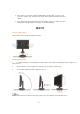
• Please make sure to clean the cabinet regularly with the provided cloth , you can use softcleanser to clean the stain , instead of severe spray cleanser which will cauterize the monitor cabinet. • Dont leak liquid into monitor which will result in the damage of chassis or component. Please unplug before cleaning ,and do not scratch the screen with hard things. SETUP Setup the stand and base Please setup or remove the base following below steps.
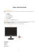
Attaching the Cables Cable Connections On Back of Monitor and Computer 1. Power 2. Audio 3. DVI 4. Analog 5. USB up 6. USB down x 3 Turn off your computer before performing the procedure below. 1. Connect the power cable to the AC port on the back of the monitor. 2. Connect one end of the 15-pin D-Sub cable to the back of the monitor and connect the other end to the computer's D-Sub port. 3. Turn on your monitor and computer. If your monitor displays an image, installation is complete.
This monitor can be attached to a wall mounting arm you purchase separately. Disconnect power before this procedure. Follow these steps: 1. Remove the base. 2. Follow the manufacturer's instructions to assemble the wall mounting arm. 3. Place the wall mounting arm onto the back of the monitor. Line up the holes of the arm with the holes in the back of the monitor. 4. Insert the 4 screws into the holes and tighten. 5. Reconnect the cables.
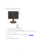
USING THE MONITOR Setting the Optimal Resolution The recommended resolution for this monitor is 1680 by 1050. To setup the monitor to this resolution, follow the steps below. 1. Click START. 2. Click SETTINGS. 3. Click CONTROL PANEL. 4. Double click DISPLAY. 5. Click SETTINGS. 6. Set the resolution SLIDE-BAR to 1680 by 1050. External Controls Press the power button to turn the monitor on or off. The other control knobs are located at front panel of the monitor (See Figure ).
1) Press the MENU-button ( ) to activate the OSD window. 2) Press or to navigate through the functions. Once the desired function is highlighted, press the MENU-button to activate sub-menu . Once the desired function is highlighted, press MENU-button to activate it. 3) Press or to change the settings of the selected function. Press or to select another function in sub-menu . Press AUTO( ) to exit . If you want to adjust any other function, repeat steps 2-3.
What is DCB? Dynamic Color Boost (DCB) is an advanced color adjustment technology. Through analyzing RGB signals, DCB creates more vivid and natural images to suit various color environment needs. DCB has two types of color enhancers: “Color Boost” and “Picture Boost” .
Full Enhance: When "Full Enhance" is turned on, the color saturation of the entire screen is fully enriched, thus all colors become more vibrant. Nature Skin: When "Natural Skin" is turned on, the red and yellow colors are enriched automatically, thus presents human skin with more natural and truer colors. "Natural Skin" setting is ideal for viewing human portrait and detailed skin texture.
Green Field: When "Green Field" is turned on, the green color is enriched so that football field and mountain landscape would look more natural and fresh. “Green Field” setting is ideal for watching mountain scenery and outdoor sports. Sky Blue: When"Sky Blue" is turned on, the color blue is being fine-tuned so that the sky or ocean landscape will look more vivid and in-depth. "Sky Blue" setting is ideal for viewing sky and ocean images. Auto Detect: picture.
Demo: Screen divided into two for demonstration purposes. 2) How to use Picture Boost? Users can change the color settings of a self-selected zone on the screen. The size and position of the selected zone can also be adjusted. "Picture Boost" is located in the fifth icon labeled "Picture Boost" in the OSD menu. Turn on "Bright Frame" to select a zone on the screen to be enhanced.
displayed content in more depths. By increasing the darkness of the dark areas and the brightness of the bright areas, contrast ratio is uplifted to exceed 2000:1. DCR value varies subject to the original CR values of the LCD module. The higher the original CR, the higher DCR can be achieved. DCR is great for watching movie or video contents. How to Use DCR? Go to the first OSD icon labeled "Luminance", turn on or off DCR as desires.
Internet Game Movie Sports Gamma1 Gamma2 Gamma3 Off On Internet Mode Game Mode Movie Mode Sports Mode Adjust to Gamma1 Adjust to Gamma 2 Adjust to Gamma 3 Disable dynamic contrast ratio Enable dynamic contrast ratio Image Setup Clock 0-100 Focus 0-100 H.Position V.Position Color Temp. Warm Normal Cool sRGB 0-100 0-100 Adjust picture Clock to reduce Vertical-Line noise. Adjust Picture Phase to reduce Horizontal-Line noise Adjust the verticalposition of the picture.
Extra Input Select Auto Config Reset DDC-CI Digital Analog yes or no yes or no Select Digital Sigal Source as Input Select Analog Sigal Source as Input Auto adjust the picture to default Reset the menu to default Turn ON/OFF DDC-CI Support Show the information of the main image and subimage source Information LED Indicators Status Full Power Mode Active-off Mode LED Color Green or Blue Orange or red Camera Software .
DRIVER INSTALLATION GUIDE Windows 2000 1. Start Windows® 2000 2. Click on the 'Start' button, point to 'Settings', and then click on 'Control Panel'. 3. Double click on the 'Display' Icon. 4. Select the 'Settings' tab then click on 'Advanced...'. 5. Select 'Monitor' - If the 'Properties' button is inactive, it means your monitor is properly configured. Please stop installation. - If the 'Properties' button is active. Click on 'Properties' button. Please follow the steps given below. 6.
dialog box. Windows Vista 1. Start Windows® Vista 2. Click the Start button; select and click on 'Control Panel'. 3. Select and click on 'Hardware and Sound' 4. Choose 'Device Manager' and Click on 'Update device drivers'. 5. Select 'Monitor' and then right click on 'Generic PnP Monitor'. 6. Click on 'Update Driver Software'. 7. Select 'Browse my computer for driver software'. 8. Click the 'Browse'button and choose the drive in which you've placed the disk. Example:(CDROM Drive:\\Lcd\PC\drivers\). 9.
Missing one of the primary colors (RED, GREEN, or BLUE) Screen image is not centered or sized properly Picture has color defects (white does not look white) Horizontal or vertical disturbances on the screen • Make sure the monitor's video cable is properly connected to the computer. • Inspect the monitor's video cable and make sure none of the pins are bent. • Make sure your computer is operational by hitting the CAPS LOCK key on the keyboard while observing the CAPS LOCK LED.
Vertical scan range Vertical scan Size(Maximum) Optimal preset resolution Highest preset resolution Plug & Play Input Connector 56 Hz - 75 Hz 290.58mm 1680 x 1050 (60 Hz) 1680 x 1050 (60 Hz) VESA DDC2B/CI D-Sub 15pin & DVI-D Analog: 0.7Vp-p(standard), 75 OHM, Positive & DVI-D Input Video Signal Digital Interface (TMDS) Power Source 100~240VAC, 47~63Hz Active < 49W Power Consumption Standby < 1W Speakers 2 x 1.
640x480 640x480 800x600 800x600 800x600 800x600 1024x768 1024x768 1024x768 1280x1024 1280x1024 1680x1050 SVGA XGA SXGA WSXGA 37.861 37.5 35.156 37.879 48.077 46.875 48.363 56.476 60.023 63.981 79.976 65.29 72 75 56 60 72 75 60 70 75 60 75 60 Pin Assignments Pin Number 1 2 3 4 5 6 7 8 9 10 11 12 13 14 15 15-Pin Side of the Signal Cable Video-Red Video-Green Video-Blue N.C. Ground GND-R GND-G GND-B +5V Detect Cable N.C. DDC-Serial data H-sync V-sync DDC-Serial clock Pin No. Signal Name Pin No.
7 DDC Data 15 Ground(for+5V) 23 TMDS Clock + 8 N.C. 16 Hot Plug Detect 24 TMDS Clock Plug and Play Plug & Play DDC2B Feature This monitor is equipped with VESA DDC2B capabilities according to the VESA DDC STANDARD. It allows the monitor to inform the host system of its identity and, depending on the level of DDC used, communicate additional information about its display capabilities. 2 The DDC2B is a bi-directional data channel based on the I C protocol.