2230Fm User Manual 1. Preface About This Guide This guide describes the monitor's features, setup, and operation. lnformation in this document is subject to change without notice. The sections are as follows: • • • • • • • Safety Instructions: lists safety information. Setup: describes the initial setup process. Using the Monitor: gives an overview of how to use the monitor. Driver Technical Support : provides tips and solutions for common problems.
. Safety Introduction FCC Notice FCC Class B Radio Frequency Interference Statement WARNING: (FOR FCC CERTIFIED MODELS) NOTE: This equipment has been tested and found to comply with the limits for a Class B digital device, pursuant to Part 15 of the FCC Rules. These limits are designed to provide reasonable protection against harmful interference in a residential installation.
Precautions WARNING: Use of controls, adjustments, or procedures other than those specified in this documentation may result in exposure to shock, electrical hazards, and/or mechanical hazards. Read and follow these precautions when connecting and using your computer monitor: PRECAUTIONS • • • • • • • • • • • • • • . Do not use the monitor near water, e.g. near a bathtub, washbowl, kitchen sink, laundry tub, swimming pool or in a wet basement.
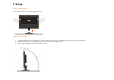
3. Setup Setup the stand and base Please setup or remove the base following below steps. Adjusting Viewing Angle • • • For optimal viewing it is recommended to look at the full face of the monitor, then adjust the monitor's angle to your own preference. Hold the stand so you do not topple the monitor when you change the monitor's angle. You are able to adjust the monitor's angle from -5°to 20 °.
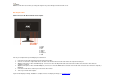
NOTE: Do not touch the LCD screen when you change the angle. It may cause damage or break the LCD screen. Attaching the Cables Cable Connections On Back of Monitor and Computer 1. Power 2.HDMI 3. DVI 4. Analog 5. Audio 6. Earphone 7. USB Turn off your computer before performing the procedure below. 1. 2. 3. 4. 5. 6. Connect the power cable to the AC port on the back of the monitor. Connect one end of the 15-pin D-Sub cable to the back of the monitor and connect the other end to the computer's D-Sub port.
Attaching Wall Mounting Arm Preparing to Install An Optional Wall Mounting Arm This monitor can be attached to a wall mounting arm you purchase separately. Disconnect power before this procedure. Follow these steps: 1. 2. 3. 4. 5. Remove the base. Follow the manufacturer's instructions to assemble the wall mounting arm. Place the wall mounting arm onto the back of the monitor. Line up the holes of the arm with the holes in the back of the monitor. Insert the 4 screws into the holes and tighten.
4. Using the Monitor Setting the Optimal Resolution The recommended resolution for this monitor is 1680 by 1050. To setup the monitor to this resolution, follow the steps below. 1. 2. 3. 4. 5. 6. Click START. Click SETTINGS. Click CONTROL PANEL. Double click DISPLAY. Click SETTINGS. Set the resolution SLIDE-BAR to 1680 by 1050. External Controls Press the power button to turn the monitor on or off. The other control knobs are located at front panel of the monitor (See Figure ).
OSD Settings • • • • • • • • • • • Press the Menu (Power) button to activate the OSD window. Press left, right, up, down button to navigate through the functions. Once the desired function is highlighted, press the Menu (Power) button to activate sub-menu . In sub-menu, Press up, down button to navigate through the functions. Once the desired function is highlighted, press , button to button to change the setting. Press Menu (Power) button to return to superior menu.
DCB Adjustment What is DCB? Dynamic Color Boost (DCB) is an advanced color adjustment technology. Through analyzing RGB signals, DCB creates more vivid and natural images to suit various color environment needs. DCB has two types of color enhancers: “Color Boost” and “Picture Boost” .
Full Enhance: When "Full Enhance" is turned on, the color saturation of the entire screen is fully enriched, thus all colors become more vibrant. Nature Skin: When "Natural Skin" is turned on, the red and yellow colors are enriched automatically, thus presents human skin with more natural and truer colors. "Natural Skin" setting is ideal for viewing human portrait and detailed skin texture.
Green Field: When "Green Field" is turned on, the green color is enriched so that football field and mountain landscape would look more natural and fresh. “Green Field” setting is ideal for watching mountain scenery and outdoor sports. Sky Blue: When"Sky Blue" is turned on, the color blue is being fine-tuned so that the sky or ocean landscape will look more vivid and in-depth. "Sky Blue" setting is ideal for viewing sky and ocean images.
Auto Detect: Demo: When “Auto Detect” is turned on, every pigment will be detected and self-adjusted to render a lively picture. Screen divided into two for demonstration purposes. 2) How to use Picture Boost? Users can change the color settings of a self-selected zone on the screen. The size and position of the selected zone can also be adjusted. "Picture Boost" is located in the fifth icon labeled "Picture Boost" in the OSD menu. Turn on "Bright Frame" to select a zone on the screen to be enhanced.
DCR Adjustment What is DCR? Dynamic Contrast Ratio (DCR) auto adjusts the brightness of the screen so users can see the darker areas of the displayed content in more depths. By increasing the darkness of the dark areas and the brightness of the bright areas, contrast ratio is uplifted to exceed 10000:1. DCR value varies subject to the original CR values of the LCD module. The higher the original CR, the higher DCR can be achieved. DCR is great for watching movie or video contents.
Function Control Illustration Luminance Brightness Contrast Adjust Range 0-100 0-100 Standard Text Eco mode Internet Game Movie Sports Description Backlight Adjustment Contrast from Digital-register. Standard Mode Text Mode Internet Mode Game Mode Movie Mode Sports Mode Gamma1 Gamma2 Gamma3 Adjust to Gamma1 Adjust to Gamma 2 Adjust to Gamma 3 Off Disable dynamic contrast ratio On Enable dynamic contrast ratio Image Setup Clock Phase H.Position 0-100 0-100 0-100 V.
Warm Normal Cool sRGB User Color Boost Full Enhance Nature Skin Green Field Sky-blue AutoDetect Demo Picture Boost Frame Size Brightness Contrast Hue Saturation Position Bright Frame OSD Setup H.Position V.Position Timeout Transparence Language Extra Input Select Red Green Blue Recall Warm Color Temperature from EEPROM. Recall Normal Color Temperature from EEPROM. Recall Cool Color Temperature from EEPROM. Recall SRGB Color Temperature from EEPROM.
Exit Exit Exit the main OSD Notes: 1)If the product has only one signal input, the item of "Input Select" is disable to adjust. 2)If the product screen size is 4:3 or input signal resolution is wide format, the item of "Image Ratio" is disalbe to adjust. 3)One of DCR, Color Boost, and Picture Boost functions is active, the other two function is turned off accordingly.
Luminance Adjust Range Description Contrast 0-100 Contrast from Digital-register.
2. Image setup Image Setup Adjust Range Description Clock 0-100 Adjust picture Clock to reduce Vertical-Line noise. Phase 0-100 Adjust Picture Phase to reduce Horizontal-Line noise H.Position 0-100 Adjust the verticalposition of the picture. V.Position 0-100 Adjust the horizontal position of the picture.
3. Color Temperature Color Temp. Preset User Reset Adjust Range Warm Normal Cool sRGB Description Recall Warm Color Temperature from EEPROM. Recall Normal Color Temperature from EEPROM. Recall Cool Color Temperature from EEPROM. Recall SRGB Color Temperature from EEPROM. Red Red Gain from Digital-register Green Green Gain Digital-register.
4. Color Boost Color Boost Adjust Range Description Full Enhance on or off Disable or Enable Full Enhance Mode Nature Skin on or off Disable or Enable Nature Skin Mode Green Field on or off Disable or Enable Green Field Mode Sky-blue on or off Disable or Enable Sky-blue Mode AutoDetect on or off Disable or Enable AutoDetect Mode Demo Disable or Enable Demo Reset Reset the menu to default Remarks: 1) There is only one item can be set to “on” except Demo.
5. Picture Boost Picture Boost Adjust Range Description Bright Frame on or off Disable or Enable Bright Frame Frame Size 14-100 Adjust Frame Size Brightness 0-100 Adjust Frame Brightness Contrast 0-100 Adjust Frame Contrast H. position 0-100 Adjust Frame horizontal Position V.position 0-100 Adjust Frame vertical Position Reset Reset the menu to default Remarks: 1) Only when Bright Frame is set to “on”, the other 5 items can be adjusted.
6.
7.
8. Help On this page, you can find the information of the monitor . Welcome to link our website and send email to us if you have any problem. Compatibility : i-Menu supports major graphic cards of ATI, Nvidia, Intel, VIA(S3). Please contact with us if your graphic card was not supported i-Menu software.
DMP Function( (Digital Media Player) ) Pls follow up the steps below and start your DMP function . 1 , Input Interface: 1) 4 in 1 memory card x1: Support SD / MMC / MS / xD memory cards 2) USB host 2, Support file format : Photo : *.jpg, *.bmp, *.png, *.gif *.tiff Audio : *.MP3, *.WMA , *.WAV Video : *.mpg, *.dat, *.avi, *.rm , *.
2) Operation guide with key button • • • • • • • • • • Turn on the monitor . Incert one of the cards (SD/MS/MMC/XD) into the 4-in-1 slot or USB Host . press button to activate the OSD source menu . press button continuously untill DMP function is selected , then press the Power button to enter into DMP interface . In DMP main interface, press or for function selection . Press button to enter into the sub-menu for input selection . Press button to enter into the file list .
5. Drivers Windows 2000 1. Start Windows® 2000 2. Click on the 'Start' button, point to 'Settings', and then click on 'Control Panel'. 3. Double click on the 'Display' Icon. 4. Select the 'Settings' tab then click on 'Advanced...'. 5. Select 'Monitor' - If the 'Properties' button is inactive, it means your monitor is properly configured. Please stop installation. - If the 'Properties' button is active. Click on 'Properties' button. Please follow the steps given below. 6.
Windows XP 1. Start Windows® XP 2. Click on the 'Start' button and then click on 'Control Panel'. 3. Select and click on the category 'Printers and Other Hardware' 4. Click on the 'Display' Item. 5. Select the 'Settings' tab then click on the 'Advanced' button. 6. Select 'Monitor' tab - If the 'Properties' button is inactive, it means your monitor is properly configured. Please stop installation. - If the 'Properties' button is active, click on 'Properties' button. Please follow the steps below. 7.
6. Technical Support Frequently Asked Questions Problem & Question • Power LED Is Not ON • No Plug & Play Picture Is Fuzzy & Has Ghosting Shadowing Problem Picture Bounces, Flickers Or Wave Pattern Is Present In The Picture • Possible Solutions Make sure the power button is ON and the Power Cord is properly connected to a grounded power outlet and to the monitor. In order for the Plug & Play feature of the monitor to work, you need a Plug & Play compatible computer & video card.
7. Product Information Specifications Model number 2230Fm Driving system TFT Color LCD Viewable Image Size 558.68mm diagoanl Pixel pitch 0.282mm(H) x 0.282mm(V) LCD Panel Video R, G, B Analog lnterface & Digital Interface, HDMI Separate Sync. H/V TTL Display Color 16.7M Colors Dot Clock 165 MHz Horizontal scan range 31 kHz - 83 kHz Horizontal scan 473.76mm Size(Maximum) Vertical scan range 56 Hz - 76 Hz Vertical scan Size(Maximum) 296.
EPA ENERGY STAR ® ENERGY STAR® is a U.S. registered mark. As an ENERGY STAR® Partner, AOC International (Europe) GmbH has determined that this product meets the ENERGY STAR® guidelines for energy efficiency.
Pin Assignments Pin Number 1 2 3 4 5 6 7 8 9 10 11 12 13 14 15 Pin No. 1 2 3 4 5 6 7 8 15-Pin Side of the Signal Cable Video-Red Video-Green Video-Blue N.C. Detect Cable GND-R GND-G GND-B +5V Ground N.C. DDC-Serial data H-sync V-sync DDC-Serial clock Signal Name TMDS Data 2TMDS Data 2+ TMDS Data 2/4 Shield TMDS Data 4TMDS Data 4+ DDC Clock DDC Data N.C. Pin No.
Pin No. 1 2 3 4 5 6 7 8 Signal Name TMDS Data 2+ TMDS Data 2 Shield TMDS Data 2 TMDS Data 1+ TMDS Data 1Shield TMDS Data 1 TMDS Data 0+ TMDS Data 0 Shield Pin No. 9 10 11 12 13 14 15 16 TMDS TMDS TMDS TMDS Signal Name Data 0 Clock + Clock Shield Clock Pin No. 17 18 19 Signal Name DDC/CEC Ground +5V Power Hot Plug Detect CEC Reserved (N.C. on device SCL SDA Plug and Play Plug & Play DDC2B Feature This monitor is equipped with VESA DDC2B capabilities according to the VESA DDC STANDARD.
8.