Safety........................................................................................................................................................................ 4 National Conventions ......................................................................................................................................... 4 Power ................................................................................................................................................................
EPEAT Declaration .......................................................................................................................................... 57 Service .................................................................................................................................................................... 58 Warranty Statement for Europe........................................................................................................................
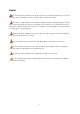
Safety National Conventions The following subsections describe notational conventions used in this document. Notes, Cautions, and Warnings Throughout this guide, blocks of text may be accompanied by an icon and printed in bold type or in italic type. These blocks are notes, cautions, and warnings, and they are used as follows: NOTE: A NOTE indicates important information that helps you make better use of your computer system.
Power The monitor should be operated only from the type of power source indicated on the label. If you are not sure of the type of power supplied to your home, consult your dealer or local power company. The monitor is equipped with a three-pronged grounded plug, a plug with a third (grounding) pin. This plug will fit only into a grounded power outlet as a safety feature.
Installation Do not place the monitor on an unstable cart, stand, tripod, bracket, or table. If the monitor falls, it can injure a person and cause serious damage to this product. Use only a cart, stand, tripod, bracket, or table recommended by the manufacturer or sold with this product. Follow the manufacturer‟s instructions when installing the product and use mounting accessories recommended by the manufacturer. A product and cart combination should be moved with care.
Cleaning Clean the cabinet regularly with the cloth provided. You can use soft-detergent to wipe out the stain, instead of strong-detergent which will cauterize the product cabinet. When cleaning, make sure no detergent is leaked into the product. The cleaning cloth should not be too rough as it will scratch the screen surface. Please disconnect the power cord before cleaning the product.
Other If the product is emitting a strange smell, sound or smoke, disconnect the power plug IMMEDIATELY and contact a Service Center. Make sure that the ventilating openings are not blocked by a table or curtain. Do not engage the LCD monitor in severe vibration or high impact conditions during operation. Do not knock or drop the monitor during operation or transportation.
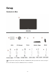
Setup Contents in Box Not all signal cables (Analog, DVI, USB, Audio, and HDMI cables) will be provided for all countries and regions. Please check with the local dealer or AOC branch office for confirmation.
Setup Stand & Base Please setup or remove the base following the steps as below.
Adjusting Viewing Angle For optimal viewing it is recommended to look at the full face of the monitor, then adjust the monitor's angle to your own preference. Hold the stand so you will not topple the monitor when you change the monitor's angle. You are able to adjust the monitor's angle from -5°to 20 °. NOTE: Do not touch the LCD screen when you change the angle. It may cause damage or break the LCD screen.
Connecting the Monitor Cable Connections On Back of Monitor and Computer: 1. Power 2. Analog (DB-15 VGA cable) 3.Audio 4.HDMI To protect equipment, always turn off the PC and LCD monitor before connecting. 1. Connect the power cable to the AC port on the back of the monitor. 2. Connect one end of the 15-pin D-Sub cable to the back of the monitor and connect the other end to the computer's D-Sub port. 3. Connect the audio cable to audio in port on the back of the monitor 4.
Wall Mounting Preparing to Install An Optional Wall Mounting Arm. This monitor can be attached to a wall mounting arm you purchase separately. Disconnect power before this procedure. Follow these steps: 1 Remove the base. 2 Follow the manufacturer's instructions to assemble the wall mounting arm. 3 Place the wall mounting arm onto the back of the monitor. Line up the holes of the arm with the holes in the back of the monitor. 4 Insert the 4 screws into the holes and tighten.
Adjusting Setting Optimal Resolution Windows Vista For Windows Vista: 1 Click START. 2 Click CONTROL PANEL. 3 Click Appearance and Personalization.
5 Click Display Settings. 6 Set the resolution SLIDE-BAR to 1920 by 1080.
Windows XP For Windows XP: 1 Click START. 2 Click SETTINGS. 3 Click CONTROL PANEL. 4 Click Appearance and Themes. 5 Double click DISPLAY.
6 Click SETTINGS. 7 Set the resolution SLIDE-BAR to 1920 by 1080. Windows ME/2000 For Windows ME/2000: 1 Click START. 2 Click SETTINGS. 3 Click CONTROL PANEL. 4 Double click DISPLAY. 5 Click SETTINGS. 6 Set the resolution SLIDE-BAR to 1920 by 1080.
Hotkeys Power Press to turn on or turn off the monitor. Source (4 : 3 or wide)/ Up Press key to change the screen aspect ratio between standard 4:3 format or Wide format. When the input resolution is wide format, the aspect ratio hotkey is disabled. When the main menu or sub-menu is active, the key functions as to select up or increase value. Source hot key : When the OSD is closed, press button will be Source hot key function (Only for the models with dual or more inputs) .
OSD Setting Basic and simple instruction on the control keys. When you press the MENU button on the front control of your monitor, the On DOWN Screen Display (OSD) Main Controls window will pop up and you can then start making adjustments to your monitor's various features. Use the UP or DOWN keys to make your adjustments. Follow the steps below to activate the adjustment. 1) Press the MENU key to activate the OSD window. 2) Press UP or DOWN to navigate through the functions.
Eco mode 21
Item Eco mode Icon Function Adjust Range Description DCR Select to active Standard Select to active Standard Mode Text Select to active Text Mode Internet Select to active Internet Mode Game Select to active Game Mode Movie Select to active Movie Mode Sports Select to active Sports Mode Dynamic contrast ratio Notes : When Eco mode is not set as “Standard”, Contrast and Brightness can not be adjusted; When DCR is set as “On”, Contrast, Brightness, Eco mode and Gamma can not be adju
Color Boost 23
Item Icon Function Adjust Range Full Enhance on or off Nature Skin on or off Sky-blue on or off Green Field on or off Auto Detect on or off Demo on or off Color Boost Description Disable or Enable Full Enhance Mode Disable or Enable Nature Skin Mode Disable or Enable Sky-blue Mode Disable or Enable Green Field Mode Disable or Enable AutoDetect Mode Disable or Enable Demo Off Disable Color Boost Exit Exit to main menu Notes : Full Enhance: Natural Skin: Green Field: Sky Blue: Suitabl
Luminance 25
Item Icon Function Adjust Range Brightness 00-100 Contrast 00-100 Description Adjust to Luminance Gamma Gamma1, 2, 3 Gamma1, Gamma2, Gamma3 Exit Exit to main menu Notes : When Eco mode is not set as “Standard”, Contrast and Brightness can not be adjusted; When DCR is set as “On”, Contrast, Brightness, Eco mode and Gamma can not be adjusted.
Image Setup 27
Item Image Setup Icon Function Adjust Range Clock 00-100 Phase 00-100 H.Position 00-100 V.Position 00-100 Exit Description Adjust picture Clock to reduce Vertical-Line noise. Adjust Picture Phase to reduce Horizontal-Line noise Adjust the vertical position of the picture. Adjust the horizontal position of the picture. Exit to main menu Notes : When the input source is digital signal like DVI or HDMI, Image Setup can not be adjusted.
Color Temperature 29
Item Color Icon Function Adjust Range User Red 00-100 User Green 00-100 User Blue 00-100 Normal 7300K Warm 6500K Cool 9300K Description Red Gain from Digital-register Green Gain Digital-register. Blue Gain from Digital-register Recall Normal Color Temperature from EEPROM. Temperatu re Recall Warm Color Temperature from EEPROM. Recall Cool Color Temperature from EEPROM. Recall SRGB Color sRGB Temperature from EEPROM.
Picture Boost 31
Item Picture Boost Icon Adjust Function Range Description Adjust Frame horizontal Horizontal Position 00-100 Vertical Position 00-100 Contrast 00-100 Adjust Frame Contrast Brightness 00-100 Adjust Frame Brightness Frame Size 14-100 Adjust Frame Size Bright Frame on or off Exit Position Adjust Frame vertical Position Disable or Enable Bright Frame Exit to main menu Notes : One of DCR, Color Boost, and Picture Boost functions is active, the other two function is turned off accordingl
Extra Setting 33
Item Icon Function Adjust Range Language Extra Description Select the OSD language Reset yes or no Reset the menu to default DDC-CI yes or no Turn ON/OFF DDC-CI Support Timeout 05-120 Adjust the OSD Timeout Transparence 00-100 Adjust the transparence of OSD H. Position 00-100 Adjust the vertical position of OSD V.
Exit 35
LED Indicator Status LED Color Full Power Mode Blue Active-off Mode Orange 36
Driver Monitor Driver Windows 2000 1. Start Windows® 2000 2. Click on the 'Start' button, point to 'Settings', and then click on 'Control Panel'. 3. Double click on the 'Display' Icon. 4. Select the 'Settings' tab then click on 'Advanced...'. 5. Select 'Monitor' - If the 'Properties' button is inactive, it means your monitor is properly configured. Please stop installation. - If the 'Properties' button is active. Click on 'Properties' button. Please follow the steps given below. 6.
Windows XP 1. Start Windows® XP 2. Click on the 'Start' button and then click on 'Control Panel'. 3. Select and click on the category „Appearance and Themes‟ 4. Click on the 'Display' Item.
5. Select the 'Settings' tab then click on the 'Advanced' button. 6. Select 'Monitor' tab - If the 'Properties' button is inactive, it means your monitor is properly configured. Please stop installation. - If the 'Properties' button is active, click on 'Properties' button. Please follow the steps below. 7. Click on the 'Driver' tab and then click on 'Update Driver...' button.
8. Select the 'Install from a list or specific location [advanced]' radio button and then click on the 'Next' button. 9. Select the 'Don't Search. I will choose the driver to install' radio button. Then click on the 'Next' button. 10. Click on the 'Have disk...' button, then click on the 'Browse...' button and then select the appropriate drive F: (CD-ROM Drive). 11. Click on the 'Open' button, then click the 'OK' button. 12. Select your monitor model and click on the 'Next' button.
Windows Vista 1. Click "Start " and "Control Panel". Then, double-click on "Appearance and Personalization". 2. Click "Personalization" and then "Display Settings". 3. Click "Advanced Settings...".
4. Click "Properties" in the "Monitor" tab. If the "Properties" button is deactivated, it means the configuration for your monitor is completed. The monitor can be used as is. If the message "Windows needs..." is displayed, as shown in the figure below, click "Continue". 5. Click "Update Driver..." in the "Driver" tab. 6. Check the "Browse my computer for driver software" checkbox and click "Let me pick from a list of device drivers on my computer". 7. Click on the 'Have disk...
Windows 7 1.Start Windows® 7 2.Click on the 'Start' button and then click on 'Control Panel'. 3. Click on the 'Display' icon. 4.Ckick on the “Change display settings” button.
5.Click the “Advanced Settings” button. 6.Click the “Monitor” tab and then click the “Properties” button. 7.Click the “Driver” tab.
8. Open the "Update Driver Software-Generic PnP Monitor" window by clicking on “Update Driver... “and then click the "Browse my computer for driver software" button. 9. Select "Let me pick from a list of device drivers on my computer". 10. Click the “Have Disk” button. Click on the “Browse” button and navigate to the following directory: X:\Driver\module name (where X is the drive letter designator for the CD-ROM drive).
11. Select the "xxx.inf" file and click the “Open” button. Click the “OK” button. 12. Select your monitor model and click the “Next” button. The files will be copied from the CD to your hard disk drive. 13. Close all open windows and remove the CD. 14. Restart the system. The system will automatically select the maximum refresh rate and corresponding Color Matching Profiles.
i-Menu Welcome to “i-Menu” software by AOC. i-Menu makes it easy to adjust your monitor display setting by using on screen menus instead of the OSD button on the monitor. To complete installation, please follow the installation guide.
Troubleshoot Problem & Question Possible Solutions Make sure the power button is ON and the Power Cord is properly connected Power LED Is Not ON to a grounded power outlet and to the monitor. Is the power cord connected properly? Check the power cord connection and power supply. Is the cable connected correctly? (Connected using the D-sub cable) Check the DB-15 cable connection. (Connected using the DVI cable) Check the DVI cable connection. * DVI input is not available on every model.
The Computer Power Switch should be in the ON position. The Computer Video Card should be snugly fitted in its slot. Make sure the monitor's video cable is properly connected to the computer. Monitor Is Stuck In Active Inspect the monitor's video cable and make sure no pin is bent. Off-Mode" Make sure your computer is operational by hitting the CAPS LOCK key on the keyboard while observing the CAPS LOCK LED. The LED should either turn ON or OFF after hitting the CAPS LOCK key.
Specification General Specification model name 2436Vh Driving system TFT Color LCD Viewable Image Size 60.97 cm diagonal Pixel pitch 0.27675mm(H) x 0.27675mm(V) Video R, G, B Analog lnterface & Digital Interface Separate Sync. H/V TTL Display Color 16.7M Colors Dot Clock 148.5 MHz Horizontal scan range 30 kHz - 80 kHz Horizontal scan Size(Maximum) 531.36mm Vertical scan range 55 Hz - 75 Hz Vertical scan Size(Maximum) 298.
Depth 206mm Weight (monitor only) 5.5 kg Weight (with packaging) 7.3 kg Operating 0°to 40° Non-Operating -20°to 60° Operating 10% to 85% (non-condensing) Non-Operating 5% to 80% (non-condensing) Operating 0~ 3000m (0~ 10000 ft ) Non-Operating 0~ 5000m (0~ 15000 ft ) Temperature: Environmental Humidity: Altitude: Preset Display Modes STAND HORIZONTAL VERTICAL FREQUENCY(kHZ) FREQUENCY(Hz) RESOLUTION VGA 640×480 @60Hz 31.469 59.940 VGA 640×480 @67Hz 35.000 66.
Pin Assignments Pin Number 15-Pin Side of the Signal Cable 1 Video-Red 2 Video-Green 3 Video-Blue 4 N.C. 5 Detect Cable 6 GND-R 7 GND-G 8 GND-B 9 +5V 10 Ground 11 N.C.
Pin No. Signal Name Pin No. Signal Name Pin No. Signal Name 1 TMDS Data 2- 9 TMDS Data 1- 17 TMDS Data 0- 2 TMDS Data 2+ 10 TMDS Data 1+ 18 TMDS Data 0+ 3 TMDS Data 2/4 Shield 11 TMDS Data 1/3 Shield 19 TMDS Data 0/5 Shield 4 TMDS Data 4- 12 TMDS Data 3- 20 TMDS Data 5- 5 TMDS Data 4+ 13 TMDS Data 3+ 21 TMDS Data 5+ 6 DDC Clock 14 +5V Power 22 TMDS Clock Shield 7 DDC Data 15 Ground(for+5V) 23 TMDS Clock + 8 N.C.
Plug and Play Plug & Play DDC2B Feature This monitor is equipped with VESA DDC2B capabilities according to the VESA DDC STANDARD. It allows the monitor to inform the host system of its identity and, depending on the level of DDC used, communicate additional information about its display capabilities. The DDC2B is a bi-directional data channel based on the I2C protocol. The host can request EDID information over the DDC2B channel.
Regulation FCC Notice FCC Class B Radio Frequency Interference Statement WARNING: (FOR FCC CERTIFIED MODELS) NOTE: This equipment has been tested and found to comply with the limits for a Class B digital device, pursuant to Part 15 of the FCC Rules. These limits are designed to provide reasonable protection against harmful interference in a residential installation.
WEEE Declaration Disposal of Waste Equipment by Users in Private Household in the European Union. This symbol on the product or on its packaging indicates that this product must not be disposed of with your other household waste.Instead, it is your responsibility to dispose of your waste equipment by handing it over to a designated collection point for the recycling of waste electrical and electronic equipment.
EPEAT Declaration EPEAT is a system to help purchasers in the public and private sectors evaluate, compare and select desktop computers, notebooks and monitors based on their environmental attributes. EPEAT also provides a clear and consistent set of performance criteria for the design of products, and provides an opportunity for manufacturers to secure market recognition for efforts to reduce the environmental impact of its products. AOC believes in protecting the environment.
Service Warranty Statement for Europe LIMITED THREE-YEAR WARRANTY* AOC Color Monitors sold within Europe AOC International (Europe) GmbH warrants this product to be free from defects in material and workmanship for a period of Three (3) years after the original date of consumer purchase. During this period, AOC International (Europe) GmbH will, at its option, either repair the defective product with new or rebuilt parts, or replace it with a new or rebuilt product at no charge except as *stated below.
modified or altered; you bear the sole responsibility and liability for any such modification or alteration. ALL EXPRESS AND IMPLIED WARRANTIES FOR THIS PRODUCT (INCLUDING THE WARRANTIES OF MERCHANTABILITY AND FITNESS FOR A PARTICULAR PURPOSE) ARE LIMITED IN DURATION TO A PERIOD OF THREE (3) YEARS FOR PARTS AND LABOR FROM THE ORIGINAL DATE OF CONSUMER PURCHASE. NO WARRANTIES (EITHER EXPRESSED OR IMPLIED) APPLY AFTER THIS PERIOD.
Warranty Statement for North & South America (excluding Brazil) WARRANTY STATEMENT for AOC Color Monitors Including those Sold within North America as Specified Envision Peripherals, Inc. warrants this product to be free from defects in material and workmanship for a period of three (3) years for parts & labor and one (1) year for CRT Tube or LCD Panel after the original date of consumer purchase. During this period, EPI ( EPI is the abbreviation of Envision Peripherals, Inc.
ALL EXPRESS AND IMPLIED WARRANTIES FOR THIS PRODUCT (INCLUDING THE WARRANTIES OF MERCHANTABILITY AND FITNESS FOR A PARTICULAR PURPOSE) ARE LIMITED IN DURATION TO A PERIOD OF THREE (3) YEARS FOR PARTS AND LABOR AND ONE (1) YEAR FOR CRT TUBE OR LCD PANEL FROM THE ORIGINAL DATE OF CONSUMER PURCHASE. NO WARRANTIES (EITHER EXPRESSED OR IMPLIED) APPLY AFTER THIS PERIOD.