L&D Monitor User Manual 2352Phz www.aoc.com ©2011 AOC.All Rights Reserved.
Safety........................................................................................................................................................................ 3 National Conventions ......................................................................................................................................... 3 Power ................................................................................................................................................................
Safety National Conventions The following subsections describe notational conventions used in this document. Notes, Cautions, and Warnings Throughout this guide, blocks of text may be accompanied by an icon and printed in bold type or in italic type. These blocks are notes, cautions, and warnings, and they are used as follows: NOTE: A NOTE indicates important information that helps you make better use of your computer system.
Power The monitor should be operated only from the type of power source indicated on the label. If you are not sure of the type of power supplied to your home, consult your dealer or local power company. The monitor is equipped with a three-pronged grounded plug, a plug with a third (grounding) pin. This plug will fit only into a grounded power outlet as a safety feature.
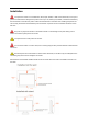
Installation Do not place the monitor on an unstable cart, stand, tripod, bracket, or table. If the monitor falls, it can injure a person and cause serious damage to this product. Use only a cart, stand, tripod, bracket, or table recommended by the manufacturer or sold with this product. Follow the manufacturer’s instructions when installing the product and use mounting accessories recommended by the manufacturer. A product and cart combination should be moved with care.
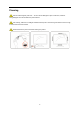
Cleaning Clean the cabinet regularly with cloth. You can use soft-detergent to wipe out the stain, instead of strong-detergent which will cauterize the product cabinet. When cleaning, make sure no detergent is leaked into the product. The cleaning cloth should not be too rough as it will scratch the screen surface. Please disconnect the power cord before cleaning the product.
Other If the product is emitting a strange smell, sound or smoke, disconnect the power plug IMMEDIATELY and contact a Service Center. Make sure that the ventilating openings are not blocked by a table or curtain. Do not engage the LCD monitor in severe vibration or high impact conditions during operation. Do not knock or drop the monitor during operation or transportation.
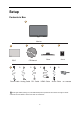
Setup Contents in Box Monitor Base CD Manual QSG * * * Power Cable Analog Cable DVI Cable * HDMI Cable Stand * Audio Cable 3D Glasses Not all signal cables (Analog, DVI, and HDMI cables) will be provided for all countries and regions. Please check with the local dealer or AOC branch office for confirmation.
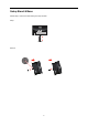
Setup Stand & Base Please setup or remove the base following the steps as below.
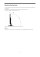
Adjusting Viewing Angle For optimal viewing it is recommended to look at the full face of the monitor, then adjust the monitor's angle to your own preference. Hold the stand so you will not topple the monitor when you change the monitor's angle. You are able to adjust the monitor's angle from -3° to 19 °. NOTE: Do not touch the LCD screen when you change the angle. It may cause damage or break the LCD screen.
Connecting the Monitor Cable Connections In Back of Monitor and Computer: 1 1. Power 2. HDMI cable 3. DVI ca ble 4. D-Sub cable 5. Audio cable /Earphone 2 3 4 5 To protect equipment, always turn off the PC and LCD monitor before connecting. 1 Connect the power cable to the AC port on the back of the monitor. 2 Connect one end of the 15-pin DVI /D-Sub/HDMI cable to the back of the monitor and connect the other end to the computer's DVI /D-Sub/HDMI port. 3 Turn on your monitor and computer.
Wall Mounting Preparing to Install An Optional Wall Mounting Arm. This monitor can be attached to a wall mounting arm you purchase separately. Disconnect power before this procedure. Follow these steps: 1 Remove the base. 2 Follow the manufacturer's instructions to assemble the wall mounting arm. 3 Place the wall mounting arm onto the back of the monitor. Line up the holes of the arm with the holes in the back of the monitor. 4 Insert the 4 screws into the holes and tighten.
Adjusting Setting Optimal Resolution Windows Vista For Windows Vista: 1 Click START. 2 Click CONTROL PANEL. 3 Click Appearance and Personalization.
5 Click Display Settings. 6 Set the resolution SLIDE-BAR to 1920 by 1080.
Windows XP For Windows XP: 1 Click START. 2 Click SETTINGS. 3 Click CONTROL PANEL. 4 Click Appearance and Themes. 5 Double click DISPLAY.
6 Click SETTINGS. 7 Set the resolution SLIDE-BAR to 1920 by 1080. Windows ME/2000 For Windows ME/2000: 1 Click START. 2 Click SETTINGS. 3 Click CONTROL PANEL. 4 Double click DISPLAY. 5 Click SETTINGS. 6 Set the resolution SLIDE-BAR to 1920 by 1080.
Hotkeys 1 3D/- 2 Volume/+ 3 Source/Auto/Exit 4 Menu/Enter 5 Power Power Press the Power button to turn on/off the monitor. '/ - Press this hotkey continuously to sele ct 2D/3D functions when the on-screen display (OSD) is unavailable. 9ROXPH/+ When there is no OSD, press Volume adjust volume. Auto / Exit / Source hot key When there is no OSD, press Auto/Source button continuously about 2 second to do auto configure. When the OSD is closed, press Source button will be Source hot key function.
OSD Setting Basic and simple instruction on the control keys. 1) Press the MENU-button to activate the OSD window. 2) Press - or + to navigate through the functions. Once the desired function is highlighted, press the MENU-button to activate it . press - or + to navigate through the sub-menu functions. Once the desired function is highlighted, press MENU-button to activate it. 3) Press - or + to change the settings of the selected function. Press AUTO to exit.
Luminance 1. Press MENU (Menu) to display menu. 2. Press - or + to select 3. Press - or + to select submenu, and press MENU to enter. (Luminance), and press MENU to enter.
+ to adjust. 4. Press - or 5. Press AUTO to exit. Brightness 0-100 Backlight Adjustment Contrast 0-100 Contrast from Digital-register.
Image Setup 1. Press MENU (Menu) to display menu. 2. Press - or + to select 3. Press - or + to select submenu, and press MENU to enter. (Image Setup), and press MENU to enter.
+ to adjust. 4. Press - or 5. Press AUTO to exit. Clock 0-100 Adjust picture Clock to reduce Vertical-Line noise. Phase 0-100 Adjust Picture Phase to reduce Horizontal-Line noise Sharpness 0-100 Adjust picture sharpness H.Position 0-100 Adjust the horizontal position of the picture. V.Position 0-100 Adjust the vertical position of the picture.
Color Setup 1. Press MENU (Menu) to display menu. 2. Press - or + to select 3. Press - or + to select submenu, and press MENU to enter. (Color Setup), and press MENU to enter.
+ to adjust. 4. Press - or 5. Press AUTO to exit. Color setup. Warm Recall Warm Color Temperature from EEPROM. Normal Recall Normal Color Temperature from EEPROM. Cool Recall Cool Color Temperature from EEPROM. sRGB Recall SRGB Color Temperature from EEPROM. Red Red Gain from Digital-register Green Green Gain Digital-register.
Picture Boost 1. Press MENU (Menu) to display menu. 2. Press - or + to select 3. Press - or + to select submenu, and press MENU to enter. (Picture Boost), and press MENU to enter.
+ to adjust. 4. Press - or 5. Press AUTO to exit. Frame Size 14-100 Adjust Frame Size Brightness 0-100 Adjust Frame Brightness Contrast 0-100 Adjust Frame Contrast H. position 0-100 Adjust Frame horizontal Position V.
OSD Setup 1. Press MENU (Menu) to display menu. 2. Press - or + to select 3. Press - or + to select submenu, and press MENU to enter. (OSD Setup), and press MENU to enter.
+ to adjust. 4. Press - or 5. Press AUTO to exit. H.Position 0-100 Adjust the horizontal position of OSD V.
Extra 1. Press MENU (Menu) to display menu. 2. Press - or + to select 3. Press - or + to select submenu, and press MENU to enter. (Extra), and press MENU to enter.
+ to adjust. 4. Press - or 5. Press AUTO to exit. Auto Select to Auto Detect input signal Analog Select Analog Signal Source as Input DVI Select DVI Source as Input HDMI Select HDMI Source as Input Auto Config yes or no Auto adjust the picture to default Image Ratio wide or 4:3 Select wide or 4:3 format for display DDC-CI yes or no Turn ON/OFF DDC-CI Support Off Timer 0~24hours Select timing to turn off the monitor.
1. VGA/DVI mode: Press the Menu key to enter the OSD menu and select the 2D/3D menu. 2D, 3D (SBS), 3D(T/B) modes are available for switchover. 2. HDMI input mode un der 2D: Press th e Menu key to enter the OSD menu and select the 2D/3D/ menu. Auto (2D), 3D (SBS) and 3 D (T/B) mo des are available for switchover. 3. HDMI input mode un der 3D: Press th e Menu key to enter the OSD menu and select the 2D/3D/ menu. Auto (3D), 3D (SBS) and 3 D (T/B) mo des are available for switchover.
Exit 1. Press MENU (Menu) to display menu. 2. Press - or 3. Press AUTO to exit. + to select (Exit), and press MENU to enter.
LED Indicator Status LED Color Full Power Mode Blue Active-off Mode red 33
Driver Monitor Driver Windows 7 1.Start Windows® 7 2.Click on the 'Start' button and then click on 'Control Panel'. 3. Click on the 'Display' icon.
4.Ckick on the “Change display settings” button. 5.Click the “Advanced Settings” button. 6.Click the “Monitor” tab and then click the “Properties” button.
7.Click the “Driver” tab. 8. Open the "Update Driver Software-Generic PnP Monitor" window by clicking on “Update Driver... “and then click the "Browse my computer for driver software" button. 9. Select "Let me pick from a list of device drivers on my computer".
10. Click the “Have Disk” button. Click on the “Browse” button and navigate to the following directory: X:\Driver\module name (where X is the drive letter designator for the CD-ROM drive). 11. Select the "xxx.inf" file and click the “Open” button. Click the “OK” button. 12. Select your monitor model and click the “Next” button. The files will be copied from the CD to your hard disk drive. 13. Close all open windows and remove the CD. 14. Restart the system.
Windows Vista 1. Click "Start " and "Control Panel". Then, double-click on "Appearance and Personalization". 2. Click "Personalization" and then "Display Settings". 3. Click "Advanced Settings...".
4. Click "Properties" in the "Monitor" tab. If the "Properties" button is deactivated, it means the configuration for your monitor is completed. The monitor can be used as is. If the message "Windows needs..." is displayed, as shown in the figure below, click "Continue". 5. Click "Update Driver..." in the "Driver" tab. 6. Check the "Browse my computer for driver software" checkbox and click "Let me pick from a list of device drivers on my computer". 7. Click on the 'Have disk...
Windows XP 1. Start Windows® XP 2. Click on the 'Start' button and then click on 'Control Panel'. 3. Select and click on the category ‘Appearance and Themes’ 4. Click on the 'Display' Item.
5. Select the 'Settings' tab then click on the 'Advanced' button. 6. Select 'Monitor' tab - If the 'Properties' button is inactive, it means your monitor is properly configured. Please stop installation. - If the 'Properties' button is active, click on 'Properties' button. Please follow the steps below. 7. Click on the 'Driver' tab and then click on 'Update Driver...' button.
8. Select the 'Install from a list or specific location [advanced]' radio button and then click on the 'Next' button. 9. Select the 'Don't Search. I will choose the driver to install' radio button. Then click on the 'Next' button. 10. Click on the 'Have disk...' button, then click on the 'Browse...' button and then select the appropriate drive F: (CD-ROM Drive). 11. Click on the 'Open' button, then click the 'OK' button. 12. Select your monitor model and click on the 'Next' button.
Windows 2000 1. Start Windows® 2000 2. Click on the 'Start' button, point to 'Settings', and then click on 'Control Panel'. 3. Double click on the 'Display' Icon. 4. Select the 'Settings' tab then click on 'Advanced...'. 5. Select 'Monitor' - If the 'Properties' button is inactive, it means your monitor is properly configured. Please stop installation. - If the 'Properties' button is active. Click on 'Properties' button. Please follow the steps given below. 6.
i-Menu Welcome to “i-Menu” software by AOC. i-Menu makes it easy to adjust your monitor display setting by using on screen menus instead of the OSD button on the monitor. To complete installation, please follow the installation guide.
e-Saver Welcome to use AOC e-Saver monitor power management software! The AOC e-Saver features Smart Shutdown functions for your monitors, allows your monitor to timely shutdown when PC unit is at any status (On, Off, Sleep or Screen Saver); the actual shutdown time depends on your preferences (see example below). Please click on "driver/e-Saver/setup.exe" to start installing the e-Saver software, follow the install wizard to complete software installation.
Screen+ Welcome to "Screen+" software by AOC, Screen+ software is a desktop screen splitting tool, it splits the desktop into different panes, each pane displays a different window. You only need to drag the window to a corresponding pane, when you want to access it. It supports multiple monitor display to make your task easier. Please follow the installation software to install it.
Troubleshoot Problem & Question Possible Solutions Power LED Is Not ON Make sure the power button is ON and the Power Cord is properly connected to a grounded power outlet and to the monitor. No images on the screen Is the power cord connected properly? Check the power cord connection and power supply. Is the cable connected correctly? (Connected using the D-sub cable) Check the DB-15 cable connection. (Connected using the DVI cable) Check the DVI cable connection.
3D Troubleshooting Ghost images that appear when viewing 3D effects may be a result of the following: 1. the displ ay unit has not bee n adj usted to its optimum resolutio n o f 1920* 1080 a t 60HZ ; if a customer complains that they are unable to locate the resolution-1920*1080, a non-standard VGA cable is possibly being used (clock and data cables have been cancelled and as a result, EDID/DDC displayed can not be read), or the graphics adapter driver is abnormal. 2.
Precautions when wearing 3D glasses: - Do not use 3D glasses as c ommon gl asses, sungl asses or protective g oggles as the y ma y dama ge your eyesight; - Do n ot kee p 3D g lasses in places that ar e too hot or cold. 3D glasses will be dama ged. Do not use damaged glasses; - Do not throw objects at 3D glasses. Do not press on or throw 3D glasses; - Use a clean, soft cloth to clean the lens (polarized film) of 3D glasses as any impurity on the cloth may scratch the glasses.
Specification General Specification Panel Resolution Model name e2352Phz Driving system TFT Color L&D Viewable Image Size 58.4cm diagonal Pixel pitch 0.265 mm(H) x 0.265 mm(V) Video R, G, B Analog lnterface,DVI,HDMI Separate Sync. H/V TTL Display Color 16.7M Colors Dot Clock 148.5 MHz Horizontal scan range 30 kHz - 83 kHz Horizontal scan Size(Maximum) 509.76 mm Vertical scan range 50 Hz - 76 Hz Vertical scan Size(Maximum) 286.
Preset Display Modes STAND$5' VGA VGA VGA SVGA SVGA SVGA SVGA XGA XGA XGA SXGA SXGA WXGA+ WXGA+ WSXGA HD *** *** IBM-MODE DOS MAC MODE VGA MAC MODE VGA HORIZONTAL FREQUENCY(KHz) RESOLUTION VERTICAL FREQUENCY(Hz) 640x480@60Hz 640x480@72Hz 640x480@75Hz 800x600@56Hz 800x600@60Hz 800x600@72Hz 800x600@75Hz 1024x768@60Hz 1024x768@70Hz 1024x768@75Hz 1280x1024@60Hz 1280x1024@75Hz 1440x900@60Hz 1440x900@60Hz 1680x1050@60Hz 1920 x1080@60Hz 1280x720@60Hz 1280x960@60HZ 31.469 37.861 37.5 35.156 37.879 48.
Pin Assignments Pin Number 15-Pin Side of the Signal Cable 1 Video-Red 2 Video-Green 3 Video-Blue 4 Ground 5 Detect Cable 6 GND-R 7 GND-G 8 GND-B 9 +5V 10 Ground 11 Ground 12 DDC-Serial data 13 H-sync 14 V-sync 15 DDC-Serial clock Pin No. Signal Name Pin No. Signal Name Pin No. Signal Name 1. TMDS Data 2- 9. TMDS Data 1- 17. TMDS Data 0- 2. TMDS Data 2+ 10. TMDS Data 1+ 18. TMDS Data 0+ 3. TMDS Data 2/4 Shield 11. TMDS Data 1/3 Shield 19.
Pin No. Signal Name Pin No. Signal Name Pin No. Signal Name 1 TMDS Data 2+ 9 TMDS Data 0 17 DDC/CEC Ground 2 TMDS Data 2 Shield 10 TMDS Clock + 18 +5V Power 3 TMDS Data 2 11 TMDS Clock Shield 19 Hot Plug Detect 4 TMDS Data 1+ 12 TMDS Clock 5 TMDS Data 1Shield 13 CEC 6 TMDS Data 1 14 Reserved (N.C.
Regulation FCC Notice FCC Class B Radio Frequency Interference Statement WARNING: (FOR FCC CERTIFIED MODELS) NOTE: This equipment has been tested and found to comply with the limits for a Class B digital device, pursuant to Part 15 of the FCC Rules. These limits are designed to provide reasonable protection against harmful interference in a residential installation.
WEEE Declaration Disposal of Waste Equipment by Users in Private Household in the European Union. This symbol on the product or on its packaging indicates that this product must not be disposed of with your other household waste.Instead, it is your responsibility to dispose of your waste equipment by handing it over to a designated collection point for the recycling of waste electrical and electronic equipment.
EPEAT Declaration EPEAT is a system to help purchasers in the public and private sectors evaluate, compare and select desktop computers, notebooks and monitors based on their environmental attributes. EPEAT also provides a clear and consistent set of performance criteria for the design of products, and provides an opportunity for manufacturers to secure market recognition for efforts to reduce the environmental impact of its products. AOC believes in protecting the environment.
Service Warranty Statement for Europe LIMITED THREE-YEAR WARRANTY* AOC Color Monitors sold within Europe AOC International (Europe) GmbH warrants this product to be free from defects in material and workmanship for a period of Three (3) years after the original date of consumer purchase. During this period, AOC International (Europe) GmbH will, at its option, either repair the defective product with new or rebuilt parts, or replace it with a new or rebuilt product at no charge except as *stated below.
modified or altered; you bear the sole responsibility and liability for any such modification or alteration. ALL EXPRESS AND IMPLIED WARRANTIES FOR THIS PRODUCT (INCLUDING THE WARRANTIES OF MERCHANTABILITY AND FITNESS FOR A PARTICULAR PURPOSE) ARE LIMITED IN DURATION TO A PERIOD OF THREE (3) YEARS FOR PARTS AND LABOR FROM THE ORIGINAL DATE OF CONSUMER PURCHASE. NO WARRANTIES (EITHER EXPRESSED OR IMPLIED) APPLY AFTER THIS PERIOD.
Warranty Statement for North & South America (excluding Brazil) WARRANTY STATEMENT for AOC Color Monitors Including those Sold within North America as Specified Envision Peripherals, Inc. warrants this product to be free from defects in material and workmanship for a period of three (3) years for parts & labor and one (1) year for CRT Tube or LCD Panel after the original date of consumer purchase. During this period, EPI ( EPI is the abbreviation of Envision Peripherals, Inc.
ALL EXPRESS AND IMPLIED WARRANTIES FOR THIS PRODUCT (INCLUDING THE WARRANTIES OF MERCHANTABILITY AND FITNESS FOR A PARTICULAR PURPOSE) ARE LIMITED IN DURATION TO A PERIOD OF THREE (3) YEARS FOR PARTS AND LABOR AND ONE (1) YEAR FOR CRT TUBE OR LCD PANEL FROM THE ORIGINAL DATE OF CONSUMER PURCHASE. NO WARRANTIES (EITHER EXPRESSED OR IMPLIED) APPLY AFTER THIS PERIOD.