32 L32H961
DIGITAL TELEVISION TRANSITION NOTICE ....................................... 1 FOR YOUR SAFETY ........................................................................................ 2 PRECAUTIONS AND REMINDERS ........................................................... 3 IMPORTANT SAFETY INSTRUCTIONS ................................................... 4 PACKAGE CONTENTS ................................................................................. 5 PREPARATION..........................................
DIGITAL TELEVISION TRANSITION NOTICE English This device contains a digital television tuner, so it should receive digital over the air TV programming, with a suitable antenna, after the end of full-power analog TV broadcasting in the United States on June 12, 2009. Some older television receivers, if they rely on a TV antenna, will need a TV Converter to receive over the air digital programming, but should continue to work as before for other purposes (e.g.
Before operating the TV please read this manual thoroughly. This manual should be retained for future reference. FCC Class B Radio Frequency Interference Statement WARNING: (FOR FCC CERTIFIED MODELS) NOTE: This equipment has been tested and found to comply with the limits for a Class B digital device, pursuant to Part 15 of the FCC Rules. These limits are designed to provide reasonable protection against harmful interference in a residential installation.
PRECAUTIONS AND REMINDERS English Place unit on even surfaces. Unplug immediately if other foreign materials are put inside TV box or if the TV fell down. Do not cover or block any vents and openings. Inadequate ventilation may shorten the life of the display unit and cause overheating. Unplug immediately if is malfunction like no picture, no video/audio,smoke and bad odor from TV. Prohibit/Avoid opening TV cabinet. Avoid direct sunlight, dusty, high humidity and smoky areas.
IMPORTANT SAFETY INSTRUCTIONS 1. 2. 3. 4. 5. 6. 7. Read these instructions. Keep these instructions. Heed all warnings. Follow all instructions. Do not use this apparatus near water. Clean only with a dry cloth. Do not block any of the ventilation openings. Install in accordance with the manufacturers instructions. 8. Do not install near any heat sources such as radiators, heat registers, stoves, or other apparatus (including amplifiers) that produce heat. 9.
English 22. 23. 24. 25. digital-to-analog converter boxes. CONSUMER ALERT – This television receiver has only an analog broadcast tuner and will require a converter box after June 12,2009,to receive over-the-air broadcasts with an antenna because of the Nation's transition to digital broadcasting.
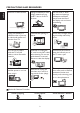
IMPORTANT: Do not apply pressure to the screen display area which may compromise the integrity of the display. The manufacturer’s warranty does not cover user abuse or improper installations. ATTACHING THE BASE IMPORTANT: The Base of the HDTV must be assembled prior to usage. 1. Place TV unit face down on a soft and flat surface (blanket, foam, cloth, etc.) to prevent any damage to the HDTV. 2. Carefully align and insert the Base to the stand. 3.
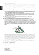
3. Remote control: Remove the cover of the battery compartment. Insert the 2 batteries supplied (Type AAA 1.5V). Please make sure to connect the power plug to the wall outlet socket after connecting the TV to the power cord! English 1. Install the base stand; place the TV on a solid surface. Min 1m Ensure that the TV is placed in a position to allow free flow of air. Do not cover the ventilation openings on the back cover.
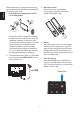
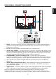
English PERIPHERAL CONNECTION GUIDE AC POWER 4 3 TV 1. HDMI – Connect the primary source for digital video such as a DVD multimedia player or set top box through this all digital connector. The white color band on the rear of the TV indicates this connection. 2. PC IN – Connect the video and audio cables from a computer here. 3. AV IN (AV/S-VIDEO) – Connect the primary source for composite video devices, such as a VCR or video game.
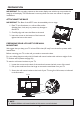
OPERATING INSTRUCTIONS English TO USE THE FRONT PANEL CONTROL 1 2 3 4 5 6 7 1 VOL + VOL +: Press to increase the sound volume level. 2. VOL - VOL - : Press to decrease the sound volume level. 3. CH ▲ CH +: Press to select the next higher Program number. 4. CH ▼ CH - : Press to select the next lower Program number. 5. MENU Menu key: Press to open or exit the OSD (on-screen display) menu. 6. INPUT Source key: Press to select the input source. 7.
POWER Press to turn ON/OFF (standby) the TV. (Note: 1.TV is never completely powered off unless physically unplugged. 2. Press to turn on TV after the power on status, LED had changed to the Blue color and stopped flashing.) SOURCE CC Press repeatedly to change the closed caption type as CC Off/ CC On/CC On With Mute. WIDE Press to choose the display aspect as: Auto, Normal, Zoom, Wide, or Cinema mode.
VIEWING MODELS ILLUSTRATIONS English Normal Mode The original content would be at the center of the screen. 16:9 Content 4:3 Content Wide Mode The original content in this mode has to fill the entire screen of the display. 16:9 Content 4:3 Content ZOOM Mode For those wide format images which are originally programmed into 4:3 frames with black bars around, this mode would stretch the image in both width and height for full display with active data.
Using the Antenna or Cable for your VCR CONNECTING EQUIPMENT English Coaxial (RF) Using Your Antenna or Digital Cable for DTV. 1. Turn off the HDTV and VCR. 2. Connect the “Output to TV”, “RF Out” or “Antenna Out” connector on the rear of your VCR to the TV connector at the rear of the HDTV. 1. Turn off the HDTV. 2. Connect the coaxial (RF) connector from your antenna or digital cable (out-of-thewall, not from the Cable Box) to the TV connector. 3. Turn on the HDTV and VCR. 4.
English Connecting Your HDTV Set-Top Box For HDTV Set-Top Boxes with DVI Using HDMI 1. Turn off the HDTV and HDTV Set-Top Box. HDTV Set-Top Boxes that have a HDMI digital interface should be connected to the HDMI input of the LCD HDTV for optimal results. 2. Using a HDMI-DVI cable, connect the DVI end to your HDTV Set-Top Box and the HDMI end to the HDMI Input at the rear of the HDTV. Connecting your HDTV Set-Top Box (Best) 3. Turn on the HDTV and HDTV Set-Top Box. 4.
Connecting Your Basic Set-Top Box Connecting your HDTV Set-Top Box (Better): Using Composite Video English Using Component Video 1. Turn off the HDTV and Set-Top Box. 1. Turn off the HDTV and HDTV Set-Top Box. 2. Using an AV Cable, connect the Video (yellow color) connector on your Set-Top Box to the corresponding Video (yellow color) connector in the AV group at the rear of the HDTV. 2.
Connecting your DVD Player (Best) 1. Turn off the HDTV and Set-Top Box. 1. Turn off the HDTV and DVD player. 2. Using a Coax (RF) cable, connect one end to the TV OUT (RF) on your Set Top Box and the other end to the TV input at the rear of the HDTV. 2. Connect a HDMI cable to the HDMI output of your DVD player and the other end to the HDMI Input at the rear of the HDTV. 3. Turn on the HDTV and Set-Top Box. 3. Turn on the HDTV and DVD player. 4.
Using S-Video (AV) Connecting your DVD Player (Better) Connecting your DVD Player (Good): 1. Turn off the HDTV and DVD player. 1. Turn off the HDTV and DVD player. 2. Connect the S-Video jack on the rear of your DVD player to the S-Video jack in the AV group on the rear of the HDTV. 3.
Using Composite (AV) Video Connecting Your VCR or Video Camera Connecting your DVD Player (Good) English 1. Turn off the HDTV and VCR or Video Camera. 1. Turn off the HDTV and DVD player. 2. Connect the Video (yellow color) connector on your DVD player to the Video (yellow color) connector in the AV group. 3. Connect the R (red color) and L (white color) audio connectors on your DVD player to the corresponding R (red color) and L (white color) audio input connectors in the AV group. 4.
Connecting Your External Sound 1. Turn off the HDTV and PC. 1. Turn off the HDTV and Sound Device. 2. Connect a 15-pin D-Sub RGB (VGA) cable to the RGB output of your PC and the other end to the VGA input at the rear of the HDTV. 2. Connect the Audio Out jack or SPDIF jack on the rear of HDTV. English Connecting to a PC 3.
TO USE THE MENUS 7. FAV Channel Setting: Show the Favorite Channel List. User can edit (add/delete) the favorite channels. English 1. Press the MENU/EXIT button to display or close the main menu VIDEO MENU 2. Use the Navigation Ring to move around to select, adjust or confirm an item in the OSD (On Screen Display) menu. The Video menu in most source modes shows as below. It provides several video adjustment items for user fine tuning the video display.
10. SRS: Solution of processing surround sound effect for playback over two speakers.Select On for optimizing bass/ treble performance and intelligibility.Select Off for keeping current audio performance level. The Audio menu in TV mode shows as below. It provides audio adjustment for user to modify the audio setting. Audio language setting is only available with ATSC TV source, the option is disable under other source modes. 11. Preset: Restore the default audio settings.
3. Advanced Video: Provide the Noise Reduction, Adaptive Contrast, and DCR for enhancing video quality. English sub-menu, the parental control function is working. The inhibitive channels or source signals can be un-lock through pressing the V-CHIP key on the remote control and then key in the correct password. Note: This feature is only available in TV, Composite and S-Video source modes. (The default password is: 0 0 0 0.
8. Analog Captions: Select an analog caption options. (CC 1-4 / TEXT 1-4) 9. Digital Captions: Select a digital caption options. (Service 1-6) [Preset] – Restore the default component setting values. 10.Digital Captions Setup: Provide numerous options for setting the digital closed caption style in the sub-menu. 13. Reset to Default: Restore all the default settings. [Style] – Set to Automatic or Custom mode. If Custom mode is selected, user can modify the detail styles described below.
Regulatory Notices – Federal Communications Commission Notice This equipment has been tested and found to comply with the limits for a Class B digital device, pursuant to part 15 of the FCC Rules. These limits are designed to provide reasonable protection against harmful interference in a residential installation. This equipment generates, uses, and can radiate radio frequency energy and, if not installed and used in accordance with the instructions, may cause harmful interference to radio communications.
Component INPUT: Rear Component x2: Y: 1V(p-p), 75 ohm, including sync. Pr/Cr: ±0.35V(p-p), 75 ohm Pb/Cb: ±0.35V(p-p), 75 ohm AUDIO: 300mv(rms) Supported resolutions:1080i, 720p, 480p, 480i HDMI Terminals: HDMI INPUT: Rear HDMI x2; Side HDMI x2 HDCP compliant E-EDID compliant Supported scan rates: 1080p, 1080i, 720p, 480p, 480i NOTE * This model complies with the specifications listed below. * Designs and specifications are subject to change without notice.
BEFORE CALLING SERVICE English Please make these simple checks before calling service. These tips may save you time and money since charges for receiver installation and adjustments of customer controls are not covered under your warranty. Symptoms Items to Check and Actions to follow “Ghost ” or double image *This may be caused by obstruction to the antenna due to high rise buildings or hills. Using a highly directional antenna may improve the picture.
HDTV HDTV displays are technically defined as being capable of displaying a minimum of 720p or 1080i active scan lines. HDMI Inputs High-Definition Multimedia Interface Audio / Video Inputs Located on the rear of the receiver, these connectors (RCA phono type plug) are used for the input of audio and video signals. Designed for use with VCRs (or other accessories) in order to receive higher picture resolution and offer sound connection options.
English 27